
|
Archerotor Antenna Rotator (150-1225B) was the TDP2, which was made by Antenna Craft. It was imported and OEM supplied by Antenna Craft to Radio Shack.
This page contains a brief description of the Archerotor Antenna Rotator. It also contains a Instruction Manual. The description is written by me, but the instructions are from Radio Shack. The instructions were obtained as simple text files through their Faxback system. I just reformatted them for easier reading.
Description
The overall rotator system consists of a Rotator Control Unit, Rotator Drive Unit, and a length of 3-conductor, #20 AWG, cable. The Rotator Control unit is powered by 120 Volt, 60 Hz, AC power and is intended to reside in your house. The Rotator Drive Unit is powered from the Rotator Control Unit via the 3-conductor, #20 AWG, cable. It is intended to be mounted on a antenna mast.
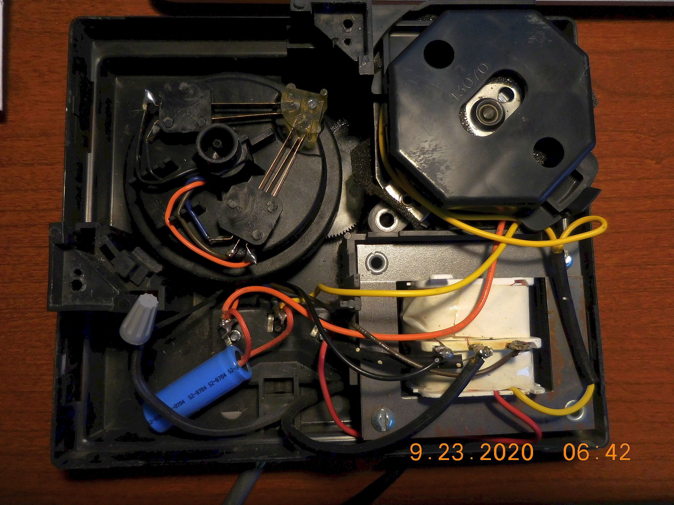
The Rotator Control Unit contains a transformer, with two 18 Volt secondary windings, a 130µF/30VAC capacitor, and a 4-pole, 18vac, motor. One of the secondary windings is used to power the split-phase motor in the Rotator Control Unit. The other winding powers the split-phase motor in the Rotator Drive Unit. In the Rotator Control Unit, the motor is geared down and drives the direction indicator disk at 1 RPM. The direction indicator disk contains the switches that determine the direction of rotation for the motor in the Rotator Control Unit and the Rotator Drive Unit.
The Rotator Drive Unit contains a split-phase motor and gear reduction, that is identical to the Rotator Control Unit. This then directly drives the antenna mast. Because split-phase motor and gear reduction is identical in both units, the direction indicator disk in the Rotator Control Unit and the Rotator Drive Unit would turn in unison. Or, as it is referred to in the Instruction Manual, "Synchronized". The two units do get out of sync after a while and require re-syncing, as described in the Synchronizing and Testing section below.
The motors are operated by contacts, S1 and S2, that are mounted on the direction indicator disk. These switches are operated by a plastic cam that rides on the inside of the direction dial. The direction dial has a detent. When the switch cam rests in the detent, S1 and S2 are open and the motors are at rest. When the direction dial is moved so that the cam is not longer in the detent, the motors activate and start turning the direction indicator disk and the motor in the Rotator Drive Unit. S2 applies power to the motors and S1 determines the direction.
Observations
When I removed the top cover, two nylon (?) guides, on opposing sides of the Direction Dial, were visible. The guides were mostly triangular and held the Direction Dial in place. But the guides didn't look correct. Each of the guides were held in by two plastic tabs and a wood screw, with a beveled head. And, the screws only loosly held the guides in place because the screw hole was too big. The only thing that kept the screws in place was the fact that the hole in the guide and the mount were misalligned. So the screw kind of went in at an angle. But that was sufficient to hold the guides in place.
When I removed the guides, one of them has a small piece of rubber glued to the bottom. The Direction Dial's rim was held in contact with the bottom of the guides. The other guide appeared to have nothing glued to it. But during my observation, the opened Rotator Control Unit fell off the desk onto the carpet. It wasn't a big drop but the motor fell out. Nothing was damaged but, along with the motor, another piece rubber with glue fell out. This was the missing part from the other guide. This was a good find because the Direction Dial wasn't operating correctly. The Direction Pointer, which is under the Direction Dial, would stop erratically or not move right. Re-gluing the rubber glide fixed everything.
But, of course, this setup with the wood screws and rubber glides was not original. Someone else was mucking around inside before me. This was further confirmed when I looked up the writing on the piece of rubber. In my unit the rubber was blue and had "Asparagus" written on it, followed by a "#" and a number. Most of the number was cut off. A quick search and aparently there are blue rubber bands made with a vegetable's name on it. These are meant for the packaging industry, so they are common in any home. In fact, I use to collect the blue bands on my celery.
With the pieces of rubber band glued in place, the unit seemed to work nicely. I haven't actually performed the modification below. But if it wasn't working properly, I would have.
Modifications
This arrangement works fine when the unit is new. However, over time the plastic pieces will wear down and the unit might not operate reliably. So I looked into a couple of modifications. To replace the control switches, a simple DPDT, center off, switch could be installed. It's important that the switch be spring loaded to the center off position. That way, when you release the switch, the motors will stop.
Another modification might be to add limit switches to the direction indicator dial. This would take two microswitches. One to interrupt the ClockWise (CW) rotation and the other to interrupt the Counter ClockWise (CCW) rotation. The switches would be electrically installed in-line with the direction switch so that, the CW microswitch would interrupt the CW toggle switch and the CCW microswitch would interrupt the CCW toggle switch. Physically, the microswitches need to be mounted so that the rotating indicator disk, triggers the switches at each end of it's rotation.
Of course, either one of these modifications means that, the switch contacts mounted on the direction disk will need to be disabled. This can be done by:
- Unsoldering the common wires on S1 and S2. Then put a piece of shrink tubing on the exposed wire ends for protection.
- You could simply place some thin strips of cardboard into the switches to prevent the contacts from touching. If you do it that way, use some glue to keep the strips in place. Use only enough glue to allow the strips to be removed in the future.
- Also, the plastic cam element can easily be removed from the direction disk. This will disable the switches, but you might want to place some tubing over the center contact for S1 and one of the S2 contacts.
| (150-1225B) | Archerotor Antenna Rotator Instruction Manual | Faxback Doc. # 46240 |
Introduction
Your Archerotor lets you turn and accurately position even the largest TV antennas from inside your home. This ensures the best possible TV reception. When you turn the control's dial for the desired direction, the drive motor turns the antenna. When the antenna reaches the desired direction, the motor automatically turns off.
Important Note: For your safety, read "Important Safeguards" and all safety, installation, and operating instructions supplied with your antenna. Keep this manual for your future reference.
Preliminary Testing
Before you install the Archerotor, do the following:
In your home, temporarily connect the drive to the control. See "Wiring the Drive Motor" and "Wiring the Control" in Faxback Doc. # 46241.
Test the Archerotor as described under "Synchronizing and Testing" in Faxback Doc. # 46241.
(br/SM 2/2/98)
| (150-1225B) | Archerotor Antenna Rotator Instruction Manual Continued | Faxback Doc. # 46241 |
Installation
Use 20 gauge three wire rotator cable, such as RadioShack Cat. No. 15-1149 or 15-1150, to connect the drive to the control.
Wiring the Drive Motor
Follow these steps to wire the drive motor.
- Snap open the drive's cover using a coin or screwdriver.
- Remove the grommet and insert the rotator cable through the grommet's slot.
- Separate the cable's three wires about 1-1/2 inches down the cable and strip off about 1/2 inch of insulation from each wire.
- Connect the wide wire to Terminal 1, connect the center wire to Terminal 2,
and connect the third wire to Terminal 3.
CAUTION: Be sure there are no loose strands of wire that can short between terminals. - Recheck the wiring order and press the grommet back into the housing.
- Close the cover securely.
Wiring the Control
Follow these steps to wire the control.
- On the other end of the rotator cable, separate the wires about 1-1/2 inches down the cable and strip about 1/2 inch of insulation from each wire.
- Run the cable through the strain relief slot on the bottom of the
control and connect the wires as follows:
Connect the wide wire to Terminal 1, connect the center wire to Terminal 2, and connect the third wire to Terminal 3. - Recheck the wiring order and tighten all the terminal screws.
CAUTION: Be sure there are no loose strands of wire that could short between terminals.
WARNING: To reduce the risk of electric shock, do not remove cover. No user-serviceable parts inside. Refer servicing to qualified service personnel.
Synchronizing and Testing
Follow these steps to synchronize and test the Archerotor
- After you wire the drive and control, plug the control's power cord into a standard AC outlet (120 volts, 60 Hz).
- Turn the control's dial fully clockwise. The indicator dot on the
control's disc moves clockwise and you can hear the control's motor.
When the antenna reaches the end of rotation, the dot stops and the control turns off. - Turn the control's dial fully counterclockwise. When the dot stops and the control turns off, the control and drive are synchronized.
- Turn the control's dial to S (south) to align the two arrows on the drive.
- Disconnect the rotator cable from the control so that you can mount the drive.
Mounting the Drive
You can mount the drive on a support mast 1-1/4 inch to 2 inches in diameter. If the mast is over 5 feet long, we recommend that you use guy wires to secure the mast.
WARNING: Select a mounting location where the antenna cannot come in contact with lower lines while you install it, and where the installation cannot fall across power lines if a guy wire should fall.
- Loosen the support mast clamp nuts enough to fit the clamps over the mast.
- Lower the drive onto the mast until the cast nose of the drives housing sits on top of the mast.
- Use a 7/16-inch wrench to tighten the clamps' nuts.
CAUTION: Overtightening can deform and weaken the mast. - If you use guy wires to secure the mast, guide the wires through the two holes of the lower clamp.
Antenna Mast
Before you mount the antenna, cut the antenna mast using the following guidelines. If the antenna boom is:
- Up to 5 feet long, the mast length should not exceed 5 feet.
- Up to 8 feet long, the mast length should not exceed 3 feet.
- Over 8 feet long, the mast length should not exceed 2 feet.
- Over 8 feet long with braces, cut the antenna mast 12 inches below the point where you attach the braces to the mast.
Mounting the Antenna
Follow these steps to mount the antenna:
- Loosen the clamps on the drive's antenna mast support enough to accept the mast.
- Insert the antenna mast between the clamps. Then rotate the antenna mast until the
antenna points south, and tighten the clamp nuts.
CAUTION: Overtightening can deform and weaken the mast.
Note: When most desired stations are north, point the antenna north. If you do this, remember that the antenna points in the opposite direction from that indicated on the control. Use the direction markers as described under "Channel and Direction Markers." - Attach the antenna cable to the antenna.
Routing the Cables
If you have 75 Ohm coaxial antenna cable, tape the cable directly to the support mast.
If you have 300-Ohm twin-lead antenna cable, attach it to the antenna and support mast using stand-off insulators (not included) about every 4 feet. Twist the cable about four times between each insulator.
For either type of antenna cable, provide a generous loop at the drive to allow full rotation of the antenna.
Tape the rotator cable directly to the support mast.
Route the antenna cable and rotator cable to the location of your TV and Archerotor control. Then, connect the antenna cable to your TV and connect the rotator cable to the control. See "Wiring the Control."
Channel and Direction Markers
Use the provided channel markers to mark the control with the desired antenna position for each channel. Use the direction markers to re-label the direction indicators on the control (if you pointed your antenna north instead of south). Place each direction marker over the control's direction indicator that represents the opposite direction.
(br/GLW 2/02/98)
| (150-1225B) | Archerotor Antenna Rotator Instruction Manual Continued | Faxback Doc. # 46241 |
Operation
To rotate the antenna, turn the control's dial for the desired direction. While the antenna rotates, the indicator dot moves, indicating the direction of antenna rotation. When the antenna reaches the selected direction, it stops.
CAUTION: Do not force the control's dial fully clockwise past N or fully counterclockwise past N. Doing so might damage the control.
Repositioning Your Antenna
If a TV channel's reception gets worse after you place the channel marker for a channel, heavy winds might have moved the antenna. If this happens, reposition the antenna so that it points in the proper direction and tighten all clamps on the drive.
(br/SM 2/02/98)
(150-1225B)Faxback Doc. # 20990
Archerotor Antenna Rotator Parts List
To order parts call 1-800-843-7422 or visit your local RadioShack store (This list was generated on 07/08/2005).
| Ref # | Cat.No. | Description | NP Part # |
|---|---|---|---|
| 12 | 10578482 | CAP 130UF 2% 40VAC | CF3001 |
| 38 | 10660850 | GROMMET,FOR DRIVE HOUSING | HC0178 |
| 94 | 10676401 | PAD, DISC | HC3388 |
| 98 | 10676427 | LID, MOTOR | HC3390 |
| 95 | 10677755 | INDICATOR,DISC | HC3758 |
| 99 | 10677789 | FASTENER KIT | HC3761 |
| 10707479 | LABEL,CHANNEL MARKER | HM0347 | |
| 37 | 10713568 | HARDWARE KIT,FASTNER | HW1501225 |
| 10713568 | RT3301 FOR MAST HARDWARE | HW1501225 | |
| 36 | 10731982 | TERMINAL BOARD ASSY | J4694 |
| 123 | 10766384 | KNOB ASSY,FOR CONTROL | K2657 |
| 97 | 10804375 | MOTOR,ANTENNA ROTATOR | M4807 |
| 10804375 | M4807 | ||
| 5 | 10811388 | MOTOR,BASE | MD0265 |
| 10820264 | MANUAL,SERVICE 15-1225B | MS1501225B | |
| 10841518 | MANUAL,USERS 15-1225B | MU1501225B | |
| 9 | 11006137 | GEAR,FIRST BASE ASSEMBLY | RA2848 |
| 10 | 11006145 | GEAR,SECOND BASE ASSEMBLY | RA2849 |
| 11 | 11006152 | GEAR,THIRD BASE ASSEMBLY | RA2850 |
| Ref # | Cat.No. | Description | NP Part # |
|---|---|---|---|
| 32 | 11006160 | GEAR,FIRST MAST ASSEMBLY | RA2851 |
| 33 | 11006178 | GEAR,SECOND MAST ASSEMBLY | RA2852 |
| 34 | 11006186 | GEAR,THIRD MAST ASSEMBLY | RA2853 |
| 96 | 11035706 | PLATE/SWITCH ASSEMBLY | RJ0334 |
| 26 | 11050994 | KIT, ACCESSORY | RT3301 |
| 11050994 | THREADED POSTS (4) | RT3301 | |
| 28 | 11051000 | COVER,BASE DRIVE 2=1 PART | RT3302 |
| 29 | 11051018 | UMBRELLA,FOR BEARING RING | RT3303 |
| 30 | 11051026 | RING, BEARING | RT3304 |
| 35 | 11051034 | PLATE ASSY,MAIN | RT3305 |
| 4 | 11097698 | TRANSFORMER 110V CONTROL | TA0854 |
| 3-COND 100FT 15-1150 | W0000X | ||
| 120 | 11197704 | BASE ASSEMBLY,110 VOLTS | Z4161 |
| 11197704 | CONTROL | Z4161 | |
| 122 | 11197712 | COVER ASSY,CONTROL | Z4162 |
| 31 | 11197720 | MAST ASSY,DRIVE | Z4163 |
| 11198264 | CONTROL BOX,COMPLETE | Z4228 | |
| 85 | 11211497 | HOUSING,DRIVE | Z5816 |
| 11226347 | LOWER CLAMP, HIGH CLAMP | Z8486 |
(150-1225)Faxback Doc. # 20902
Archerotor Antenna Rotator
Troubleshooting
|
|
|
|