 External SWR Indicator
 |
This page provides details on a modification of the IC-735
SWR display capability. Overall, it's a pretty simple modification
and doesn't interfere with the original S-Meter/Power display capabilities.
The modification can be removed at any time, bringing the unit back to original.
The IC-735 has the built in capability of measuring the
SWR at the antenna terminal. While it works,
the meter is a little small and the switches are difficult to use. The PO/SET/SWR
switch is used to display the Power Output (PO), adjust the
SET position on the meter, and read the SWR.
But the switch is on the rear panel. I find it difficult to reach around the back of the unit, while trying to adjust
and view the FWD power to the SET position.
I thought it would be much easier if the FWD and REF signals
were routed to an external meter. The external meter could then have the switches needed for setting
FWD power and reading the SWR. It would be
even nicer if that meter was a cross needle meter. Then, I would only need to bring out the
FWD and REV voltages and no switches would be needed.
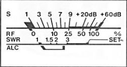
| In the transmit mode, the METER SWITCH selects one of
the three meter functions. |
| (1) | Po: |
The meter indicates the relative RF output power provided
the METER SWITCH, in the SWITCH PANEL,
is set to the PO position. |
| (2) | SET: |
Place the switch in the SET position to measure the
standing-wave ratio (SWR) of the antenna system. Adjust the
RF POWER CONTROL until the needle rests at the SET
position on the meter. |
| (3) | SWR: |
The front panel meter directly reads the antenna system SWR
after calibration as explained in step (2). |
Well, at a ham fest, I found a Workman HP202S SWR/Power Meter with
a cross needle display, for cheap. The frequency range on the box was listed as
26-28 MHz (Citizen Band). But this was blacked out and
"HF" was hand written in it's place. I didn't now whether this was
done by the manufacturer or the seller of the item. A look On-Line shows the HP202S
to be for 26-28 MHz only. But that doesn't really matter, as I only
wanted the display portion to interface to my IC-735. Then I didn't need
the rear switch to SET and then read the SWR.
| SIGNAL | MEANING |
| T8 | +8 Volts in Transmit. |
| R8 | +8 Volts in Receive. |
| SM | S-Meter Voltage to Meter. |
| ALCM | ALC Voltage to Meter. |
Below is a "mostly accurate" schematic of the section of IC-735 for
SWR sensing and display circuitry. On the right is a table that
defines the signal names that are used in the drawing. I say "mostly accurate" because there
were a few things that I chose to leave out. They didn't deter from the understanding of the circuitry,
so were unnecessary. The Sensor Unit (on the left) is located on the
Power Amplifier and the metering circuitry (on the right) is located
on the Main PCB. The FWD and
REF signals come from the sensor on the Power Amplifier
over to the Power/SWR switch (S6) on the Main PCB.
The switch selects either Power, FWD Power,
or REF Power. This is routed to, and buffered by, IC15A.
The output of IC15A is then routed through S1 and
the bilateral switch (U1-A) to the meter.
|
Calibration |