 MC6800 Morser by Robert D. Grappel and Jack Hemenway - Byte Magazine, Vol 00-14, Oct. 1976
 |
Add This 6800 MORSER to Your Amateur Radio Station
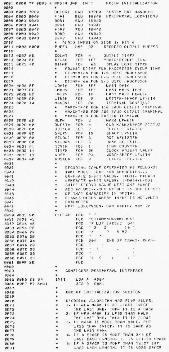
The program for MORSER shown in this article was produced by a relocating assembler designed and written by Jack Hemenway and described somewhat humorously in the August BYTE article "jack and the Machine Talk" [page 52] by authors Grappel and Hemenway. The relocatability feature allows one to put assembled code anywhere in memory without reassembly, a feature which is most useful for building large programs. One drawback of this is that relocatable addresses (denoted "R" in the listing) are always two bytes, so the programmer cannot generally make use of Motorola's Direct addressing mode, which requires addresses to be in the base page; the first 256 bytes of memory address space. Since MORSER was programmed so that both data and program code are relocatable, it is not the most compact form in which the algorithm could be expressed on a 6800. If one rewrote the program to keep all the variables in the first page of memory and used Direct addressing wherever possible, about 75 bytes of storage could be saved.
Note that, in the original code listing, some OpCodes are marked with a R, even though those OpCodes do not have a Direct addressing capability, e.g. 13 Opcodes (CLR, COM, NEG, DEC, INC, ROL, ROR, ASL, ASR, LSR, TST, JMP, JSR) can only use the Indexed or Extended mode. Yet, they are marked with an R in the original listing. - K7MEM
A great many amateur radio operators find Morse code operation a nuisance. It isn't easy to develop proficiency in copying code, and it often seems that those stations, one wants to work alone just those whose operators send code too fast to readily copy. There must be hundreds of Morse coding aids developed over the years, ranging from mechanical keys and paper tape transmitters to fancy code memories and typewriter like automatic transmitters. Nearly every advance in electronic componentry has spawned a new series of Morse code aids. Nearly all have been designed to help the operator send more effectively; the problem of reception has been more difficult to solve. Some complex circuits have been devised which can copy code, provided that it follows strict timing requirements. Truly, general code followers, circuits which can copy code with performance approaching that of a skilled human operator, are rare. They are very complex, using dozens of integrated circuits, large diode matrices, etc. The recent advent of inexpensive yet powerful microcomputers can make the dream of a relatively simple yet very general code follower possible. Why a computer? First of all, it allows one to develop and improve an algorithm by simply changing program, instead of rebuilding complicated circuitry. Second, since the computer is not restricted to running only the Morse programs, one can use the computing power for any number of other uses, limited only by the operator's creativity. This article describes a code following computer program as implemented on a Motorola 6800 microcomputer. It can copy any code speed from 3 to 60 words per minute, and can adjust to the irregularities of hand sent code. A minimal amount of external hardware is needed, and the program only takes about 600 bytes of memory. The algorithm can be converted to run on almost any 8 bit microprocessor. Since you are still reading this, you are hooked. Let's begin to dissect the program.

MORSER consists of five segments: initialization, decoding, delay timer, sampler, and terminal driver. In the program listing, lines 001-068 are initialization, lines 069-200 are decoding, 200-213 form the delay timer, 214-250 form the audio sampler, and lines 251-277 drive the output terminal. Each segment will be described in turn.
The major function of initialization is to define the variables in the program and to give them appropriate initial values. The operating system of Jack Hemenway's machine performs some of the initialization automatically at loading time, such as clearing the peripheral registers and setting the stack pointer. If the program is to be run on a system without these features, then statements to perform these functions must be added to initialization. The values of DTIME and MAXCNT must be set, based on the computer running the program. DTIME adjusts the program timing to the processor cycle time, and MAXCNT adjusts the terminal driver to the data rate of the terminal in use for output. These values are not very critical, and the program comments list typical values for these constants. Assembled, MORSER assumes a 6820 PIA at addresses 8040-8043 (hexadecimal). The peripheral interface can be relocated to suit the particular hardware configuration in use.
Only one input bit is needed; the rest of the PIA may be used for other functions. The listing also shows that an external subroutine, OUTCRT, is being used to drive a CRT terminal for output. This program is part of Jack Hemenway's system. The user of MORSER must provide a suitable routine for his or her own system. For example, the OUTEEE routine in Motorola's MIKBUG will work. The idea is that some way must be found to take a character from the A accumulator and place it appropriately on the output device. An automatic carriage return and line feed is required, as MORSER does not count the characters in a line.
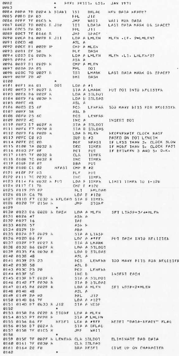
Initialization also sets up the decoding table DECTAS. The ordering of this table is the heart of MORSER. The ASCII representation of a character is placed in DECTAS at an offset generated as follows: Generate a byte with a binary 1 for every dot and 0 otherwise; generate another byte with a binary 1 for every dash and 0 otherwise. For example, the letter A (Morse - ) generates 00000010 and 00000001 respectively. Multiply the dash byte by two with a left shift and add the bytes. The result is the character offset. Using this algorithm, it is seen that A is at an offset of 4. All other Morse characters are generated in the same manner, and the rest of the table is filled with blanks. It is the function of the remainder of MORSER to convert the incoming audio signal into offsets into DECTAS, and to transfer the character representations found there to the output device.
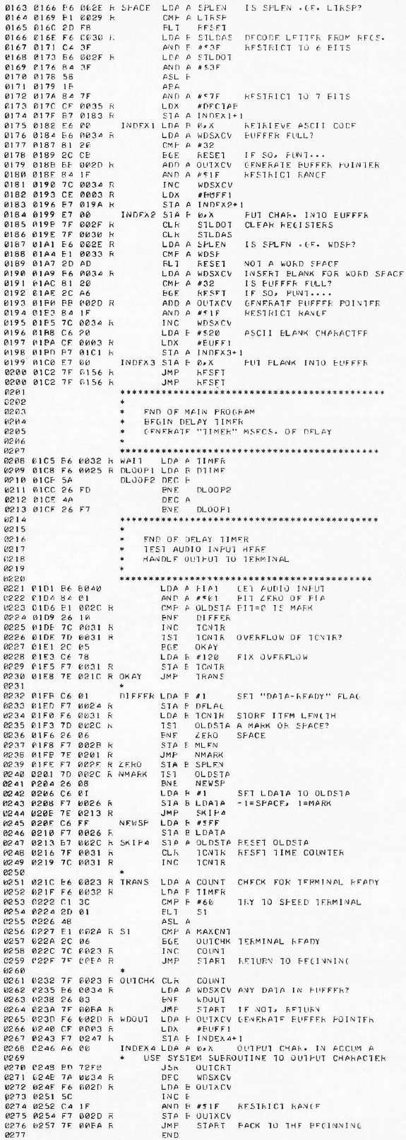
MORSER decides which inputs are dots, dashes or word spaces by sampling the audio input at intervals. The delay timer section controls the period of the sampling. This tiny section of code (only six instructions) actually consumes more than 75% of the running time of MORSER. In fact, the time spent in all other parts of MORSER is considered negligible in the design. A rough "rule of thumb" states that one word per minute of Morse code is equivalent to one dot length per second. All other code elements have lengths nominally equal to integer multiples of the dot length. MORSER is designed to sample each dot length time unit four times. Since the range of code speeds is 3 to 60 words per minute, this implies that the sampling period should range from 100 to 4 ms. The delay timer is adjusted by DTIME to count time in millisecond intervals. The variable TIMER determines how many milliseconds will be spent in the delay loops. This time is roughly the sampling period, since the longest path through the rest of the program is at most 0.3 ms. TIMER is adjusted in the decoding section to suit the speed of the code being processed. The formula 250/TIMER gives the approximate input code speed in words per minute, after the program has been running for several characters and has adjusted itself to the code.
The sampling section repeatedly tests the status of the audio input signal against its previously sampled value. If no change is found, the time counter is incremented to indicate the increased length of the signal. If a change is found, then a series of processes are done. The data ready flag is set to tell the decoder that a pulse is complete, the time counter is stored in to the mark length or space length variable, the data type (mark or space) is recorded, and the time counter is reset to one. A few notes are in order about sampling. First, the sampler assumes that an input level zero (ground) indicates the presence of an audio tone (mark), and that a one level input (high voltage) indicates no tone (space). This setup coincides with the audio processing hardware described later; but if one wishes to have a one input signify mark instead, only two simple program changes are necessary. Changing the BNE (branch on not equal to zero) instructions on lines 236 and 241 to BEQ (branch on equal to zero) instructions will accomplish the inversion. This illustrates the ease of modifying the system when it is based on a program instead of hardware. One other note: One must protect against overflows of the time counter. This Occurs when long marks or long spaces cause the counter value to exceed the maximum value representable as a positive byte. MORSER checks for such occurrences, and resets the time counter to a large positive value whenever an overflow is detected .
We come now to the decoding section. The section is a software version of algorithms abstracted from several hardware designs. It can be described by a set of five decoding rules. The length (time counter value) of the last mark received is used to determine the type of the present mark. The length of the last dash received is used to determine the type of space being received.
RULE 1. If the new mark length is at least twice the length of the last mark received, then the new mark is a dash.
RULE 2. If the new mark length is less than one half of the length of the last mark received, then the new mark is a dot.
RULE 3. If the new mark length is more than one half but less than twice the length of the last mark received, then the new mark is the same type as the old mark was.
RULE 4. If the new space length is more than 3/4 of the last dash length received, then the new space is a letter space.
RULE 5. If the new space length is longer than twice the last dash length received, then the new space is a word space.
Any other space is an element space. These rules determine the processing path of each data item returned by the sampling section. The dots and dashes are stored in memory (STLDOT and STLDAS) until a letter space is detected. Then the memory contents are converted to an offset in DECTAB, following the process previously described. The character code found in DECTAB is then transferred to the output buffer. The buffer is arranged as a 32 character first in, first out store which allows the decoding to get ahead of the output device for short periods. The detection of a word space causes the latest letter to be decoded and an extra blank character is inserted into the output buffer to provide a space between output words.
The decoding section also adjusts the TIMER value each time a dot is detected. Dots are nominally four samples long. If a dot is declared shorter than three samples, the sampling period is reduced. If a dot is declared longer than five samples, the sampling period is increased. This mechanism helps MORSER to follow changes in code speed during a message or even within characters. The flexibility of the decoding rules will allow code far from the proper timing to be decoded correctly during the adjustment process. Most decoding errors will result either in no character at all being output, or a blank being substituted for the garbled character. MORSER can handle code with wild speed variations and weightings from 10% to 90%, but it can be fooled by sufficiently erratic code. So too, however, can most human operators.
MORSER uses a programming "trick" in conjunction with indexed addressing to facilitate the decoding and output process. This occurs on lines 174 (186), 183 (195), 198 (210), 267 (279). (The numbers in parenthesis are for the listing with my assembler - K7MEM) The problem is to retrieve or store data at a particular location within a table or buffer. The starting address of the area is known, and the desired offset is calculated each time. MORSER uses the technique of modifying it self during execution. Since the program is stored in programmable memory, it can be changed just as the variables can be changed. In Motorola systems, the second byte of an instruction using indexed addressing stores an offset to be added to the index register contents to generate the final effective address for the instruction. MORSER loads the index register with the beginning of the desired table and then writes the calculated offset into the second byte of the indexed instruction. The processor adds the two, making the desired address. This works well, as long as the program is stored in programmable memory, and one is careful where one writes. If this type of trickery is to be avoided (for example, if the program is to be put into read only memory), the process of adding the offset to the base address must be done explicitly. The code in the example above, will perform the function, where X contains the starting address of the table, and accumulator A contains the offset. However, this will require, inserting the code example code in several places in the original code, and then re-assembling.
The output terminal driver makes use of the delay timer to prevent the program from exceeding the speed capabilities of the output device. A count is kept of the number of delay periods since the last character was sent to the terminal. The value of MAXCNT is set such that MAXCNT delay periods at a 60 words per minute Morse code speed are roughly equal to the recovery period of the terminal in use. If the code speed is less than 30 words per minute, then one half of MAXCNT is used to let the terminal run nearer its full speed. This counting ensures that the terminal will not receive characters faster than it is capable of handling them. The output buffer helps absorb speed variations. In cases of extreme speed variations with a very slow output terminal, a few characters may be lost. This would require input speeds of over 80 words per minute to be maintained for many characters if one used a 110 baud terminal. It is not likely that the audio processing hardware could switch at this rate, so the characters would be unreliable anyway. All slower speeds could be handled without trouble. The system subroutine used to drive the terminal is called in this section on line 392. It should not use interrupts or any timing loops, since these will upset the timing in MORSER. Since MORSER already does output timing, they are not needed anyway.
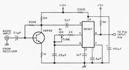
That is all there is to the MORSER program. The most critical part of the whole system is the audio input hardware. This circuit needs rapid response (since switching time for 60 words per minute code is about 13 ms), audio selectivity, immunity to noise, and immunity to varying signal levels. No optimum circuit is known by the authors. The circuit shown is a suggestion which shows promise. It uses a 567 phase locked loop tone decoder, tuned to a center frequency of about 1 KHz. The bandwidth is set at approximately 10% of the center frequency, or about 100 Hz. This circuit should switch fast enough for most code speeds, and the phase lock design gives noise immunity, for the circuit will require 10 more cycles at the correct frequency before it will switch. An input level of about 200 mV seems to give the best immunity from interfering signals and noise. The output rests at +5 V, dropping to near ground when a proper frequency tone is detected. This voltage level is read by the sampler program through the peripheral interface. This signal must be very clean, since variations will probably be decoded as extra dots and dashes. Lots of 'E's and 'T's will indicate a problem in the audio processing.
MORSER works surprisingly well, and it will be able to decode almost anything that its operator can feed it. It does not know English or radio terminology, so it cannot guess what the characters should be. It simply decodes what it "hears," and may not correct some errors that a human would recognize. It does decode the input faithfully, and that can be quite a help. Of course if you use MORSER to listen to a station using automatic code generation technology (on a clear channel) you should get perfect copy once the speed adaptation is complete.
|
The MORSER Program Listing |
The listing on the right is a copy of the MORSER program, directly from the original magazine article. Some of it is difficult to read as this is a copy, of a copy, of a copy. It's actualy unknown how many copies it is. It was assembled with Jack Hemenway's assembler. While I don't have the original assembler, I assume that specifying the code to be Relocatable, was done on the command line, as opposed to using a Pseudo-Op. Instructions that were directed to be Relocatable are marked with a "R".
The listing below is from my MC6800 SH/GAWK Cross Assembler. My assembler has a similar feature for specifying that the assembler should generate Relocatable code. That feature is invoked using the "OPT RELOC" Pseudo-Op.
Differences - You might notice that there are some differences between the original listing (above) and the listing from my assembler (below).
- At the top of the listing for my assembler, I have added the NAME Pseudo-Op, some extra comments, several Pseudo-Ops for managing the generation of S-Record and Intel Hex formatted files. Plus a Pseudo-Op that reduces the margins in the RTF (Rich Text Format) file.
- In the original listing, at line 0061, there is a FCC Pseudo-Op that doesn't have an Operand. Yet, the next line of code, line 0065, gets incremented to 00B516. What was suppose to be in that Operand? Well, I don't know. So I simply added a Operand with 7 spaces. This has two effects. It makes the address of both listings start at the same address. It also insures that there are ASCII spaces included at the end of the decoding table. I don't know if it makes a difference with the code, but it is better than leaving random data in that area.
- In the original listing, several lines of code include a "R"
to indicate that this line references a Page 0 address, and is using the
Extended mode of addressing. That's fine except that, some of
the lines of code that are marked, do not have a Direct mode
of operation. An example would be the JMP instruction on line
0001. In this instance, the instruction would use the Extended
mode, whether it was assembled Relocatable,or not. There would be no
difference. JMP will still use the same addressing mode and
there would not be any memory savings, if Relocatable was not
specified.
In the listing below, each line of code that could have used Direct mode of addressing, but is directed to use the Extended mode, is marked with an "R", followed my a decimal number. The number indicates the instance when Extended is used, instead of Direct. So the listing below shows that 52 bytes of memory could be saved, if the code was not assembled Relocatable. I have assembled it both ways and find that to be correct.
|
|