|
The Motorola Way! ... a hobbyist's review of the MEK6800D1 by Howard Berenbon, Kilobaud Mag, March 1977 |

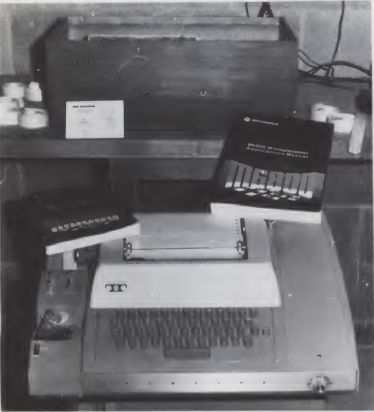
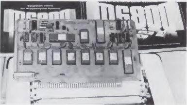
The M6800 Design Evaluation Kit from Motorola is, in my opinion, one of the best and least expensive ways for the electronic hobbyist to enter the field of microcomputing. It is available from any Motorola Semiconductor distributor for $149.00. This price includes three I/O (Input/Output) devices; two RAM (random access memory) chips, each containing 128 X 8-bits; one MC6800 Microprocessing Unit; one MCM6830L7 ROM (read only memory) which contains a program called MIKBUG* that allows you to load, display and output data for the M6800; Teletype** and RS232 circuitry for interfacing to a peripheral and a 9" x 6" printed circuit board, plated through the holes.
Along with the components, the kit supplies you with two extremely informative manuals and a number of application notes, including the assembly listing for the MIKBUG monitor program. The two manuals are the applications manual and the programming manual. The M6800 Microprocessor Applications Manual is 714 pages in length. It includes a detailed hardware section including circuitry for adding buffers and additional memory for expansion of the M6800 system. Another section details some of the very useful programming techniques of the M6800. It expands on the use of the indexed addressing and relative addressing techniques and describes programming time delays and software design of logic gates. There are some examples provided. They include a short program for use as a time delay and another used for zeroing memory. The zero memory program uses indexed addressing techniques.
The second manual provided by Motorola is the M6800 Programming Manual. It is 300 pages in length. The first part of the book describes the use of an 8K assembler which is available for use with Motorola's Exorciser microcomputer system. There are also sample programs that can be modified to run on most M6800 systems. A third section details each instruction of the M6800 in fine detail for each addressing mode, including a description of the flags which are set or reset upon execution of that instruction. If no flags are affected, then that is also indicated. The number of MPU cycles and the number of program bytes is also given for each operation.
Also provided with the kit is the M6800 Microprocessor Instruction Set Summary Card. This is a 15" x 4%" card folded into five 3" sections. It includes all of the M6800 assembly instructions and their hexadecimal equivalents for each of the five addressing modes, plus the effect that each operation has on the six condition codes.
| Construction and Operation |

Construction is fairly straightforward. Motorola does not provide a step-bystep format in their assembly instruction booklet, but they do provide a block diagram of the circuit board with component layout and a detailed circuit diagram of the basic M6800 microcomputer system. This includes all necessary I/O connections. See Fig. 1 for the circuit diagram. There is space provided on the board for adding an additional four MC6810 RAM memory chips. This allows a total of 768 words or bytes of useful memory space without modification to this single-board M6800 system.
The system may be set up for use with a Teletype, which operates at a speed of 10 characters a second, or it may be used with an RS232 format, which operates at a speed of 30 characters a second. The total cost for the M6800 system is approximately $250.00, less the cost of the Teletype or other similar terminal which is necessary for input/output. This includes the price of the design kit and power supplies, plus $50 extra for filling the board with resistors, capacitors, potentiometers, diodes, integrated circuits, IC sockets and four additional RAM chips. To prevent possible heat and static damage to the microcomputer chips, I suggest that IC sockets be used to mount them onto the printed circuit board, and when handling the chips you should be grounded. A conductive wrist strap connected to a ground is suggested.
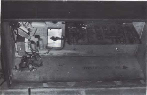
There are three power supply voltages needed to operate the M6800 system. The main board uses a highly regulated 5 V dc, 1 Amp supply. The Teletype interface requires +12 V dc, 100 mA and -12 V dc, 50 mA, both ±10%. The 5 V dc and the ±12 V dc supplies must be isolated from each other. I built the 5 V dc supply using a LM309, 5 volt, 1 Amp regulator. I used two LM340-12, 12 V dc regulators to design the ±12 V dc power supply. See Fig. 2 for the power supply circuits.
The printed circuit board is mounted vertically in an 86 pin connector (P1). The connector is mounted to a 12" x 22" piece of vectorboard. The 5 V dc power is applied to the PC board through the 86 pin connector. The ±12 V dc supply is connected to the Teletype interface through a 16 pin connector (P3).
There are two critical adjustments that must be made before proper operation of the M6800 system. The bit rate must be set up for either 10 CPS by adjusting potentiometer R23A to 9.1 msec, or for 30 CPS by adjusting potentiometer R23B to 3.3 msec. The clock frequency must be set by adjusting R9 to 450 nsec for 01 and adjusting R13 to 470 nsec for 02.
Connector P3 interfaces to the Teletype or RS232 type terminal through a 16 pin header. My system uses an ASR-33 Teletype as the terminal. The serial output, TTY common and serial input of my system are wired to an RS232 connector (DB-25S-25 pin female), which is mounted at the rear of my cabinet. A cable coming from the Teletype is wired to an RS232, 25-pin, male connector. The Teletype is wired for a 20 mA, full duplex, current loop, following the wiring diagram in the assembly manual.
Testing the microcomputer for proper operation consists of turning power on and pressing the reset push-button momentarily. The terminal should respond with a carriage return, line feed and an asterisk which indicates the MIKBUG control program is ready for input. Now you're ready for programming.
| Programming |
The maximum allowed RAM (random access memory) in the M6800 Design Evaluation Kit is 768 bytes, or words. Since the MCM6830L7 MIKBUG monitor ROM uses one RAM chip (128 bytes) as a stack, this leaves 640 bytes of memory for programming. The memory of the system may be expanded to up to 65K, but this will require additional memory chips and buffering. And 640 bytes is actually more than enough memory space for demonstrating the usefulness of the M6800 microcomputer. The secret of successful programming is in the MIKBUG monitor ROM. MIKBUG allows you to load data into memory, change the contents of memory and display the contents, punch a paper tape from memory, display the contents of the microprocessor's registers and go to target program.
MIKBUG provides a number of useful subroutines that one may incorporate in programming the M6800. Three of these subroutines are CHARIN, CHAROUT and RETURN TO MIKBUG. CHARIN is accessible by addressing the hexadecimal memory location E078 using the JSR (jump to subroutine) instruction. It allows you to input one character into accumulator A from the terminal each time the subroutine is called. CHAROUT is accessible by addressing the memory location E075. It will output one character from accumulator A to the terminal. RETURN TO MIKBUG allows control returned to MIKBUG. It is accessible by addressing the memory location E0E3.
Before going on to the programming example, here is a description of the features of MIKBUG. To load data one simply types the address of the beginning hexadecimal byte that you wish to start at. This is done by first typing an M at the terminal. MIKBUG will then type a space. Enter the desired hexadecimal address of the memory location to be opened, and the terminal will respond with a space and the contents of that memory location. The data may be changed by typing a space and then entering the desired data in hexadecimal. The terminal will respond with a carriage return, line feed and print the next consecutive memory address along with its contents. To exit this function, type a space and a carriage return. The terminal will respond with an asterisk indicating control has been returned to MIKBUG. Any number of consecutive memory locations may be displayed when using this function by simply typing any character at the terminal except a space or a carriage return, and MIKBUG will print the next address and its contents.
To display the contents of the MPU registers, type an R at the terminal, and MIKBUG will respond with the contents of registers of the M6800. Starting from the left, the first location displayed contains the condition codes, next the contents of accumulator B, the contents of accumulator A, the index register, the program counter and the stack pointer. The registers are stored on the user's stack.
To execute a program, the program counter must be initialized before a program can be run. Initialize the program counter to the address of the first byte of your program. This is done by examining memory locations on the stack at A048 and A049, which contain the contents of the program counter. Change the contents of these two bytes to the address of the first byte in your program. To execute your program type the letter G at the terminal. This is the GO command. The MPU takes the address in the program counter and begins execution at that address. To exit the program and return to MIKBUG, just press the RESET button.

A punched paper tape may be made of your program or of any part of your memory by first initializing the stack at A002 and A003 to the beginning address of your program and then entering at locations A004 and A005 the ending address of your program or block of memory. Now feed the paper tape into the punch. Return to MIKBUG by typing a space and a carriage return or by depressing the RESET button. Type the letter P at the terminal. This will turn on the paper tape punch and punch a paper tape of your program in the form accepted by your M6800 system. This program can be reloaded into your system by using the memory loader function of MIKBUG. Place the punched paper tape into the paper tape reader of your terminal. Return the system to MIKBUG control. Now type the letter L at the terminal. The tape reader will be turned on and load the contents of the paper tape into your system's memory ready for use. To run the program, initialize the program counter as described. Return to MIKBUG and type the G command.
The SWI (Software Interrupt) instruction is an interesting feature of the M6800 and is used in debugging programs. When placed in the body of a program, the program will run until the MPU encounters the SWI instruction. Then the contents of the microprocessor's registers will be printed. These values may be checked against known or calculated values to determine if your program is functioning properly. It can also be used to find problem areas in your programs by replacing one instruction in your program sequence with the SWI. Run the program. Continue to replace one instruction with the SWI until the registers fail to be displayed. Your problem will lie near the last area in which you replaced an instruction with the SWI.
