The page is mostly verbatum from the article listed below. However, I have redrawn all of the diagrams/tables, added some modifications, and comments. These additions will be ended with my call sign. There is also a section, that I added, at the bottom named Multi-Memory Morse Machine Modifications. That section describes modifications that I would make to make it easier to change the messages. - K7MEM
 A Multi-Memory Morse Machine by Kenneth D. Leininger, WA8TIW - 73 Amateur Radio Today, Dec. 1978
 |
Using a Motorola Micro
This program, a dual function aid to sending Morse code, was written on Motorola's MEK6800D2 evaluation kit. Not only is the function useful, but valuable experience is to be gained in writing a program which exercises the PIA. (No matter how large or small your system, you can't "control the world" without first stirring those I/O lines to life!)
As previously indicated, this program does two jobs: It emulates the logic of an Automatic Keyer, and also allows the fully automatic transmission of one of five pre programmed messages. All eight lines on the "A" side of the user's PIA are utilized: two for the dot (PA7) and dash (PA6) contacts of the keyer, one for the output to the keying-relay buffer (PA0), and one for each of the five message select push-buttons (PA5 to PA1). Fig. 1 indicates how simple a schematic becomes once a microprocessor system is used to displace combinational logic .
The program runs in the 256 bytes of RAM provided in the "barefoot" kit, but expansion of the kit to 512 Bytes by adding two MC6810 chips in the sockets provided is necessary for the message buffer. Of course, one could utilize the optional ROM areas on the kit once the application and messages were suitably developed.
|
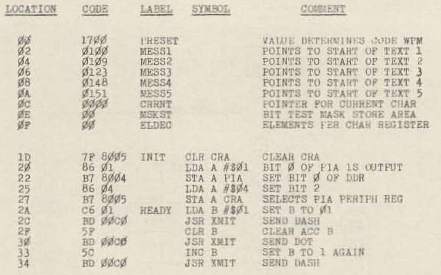
Initialization |
The program is executed at location 0010 As indicated by Fig. 2 and Program A. the PIA is configured. Then the letter "K" is sent to acknowledge a functioning system. Just how the dits and dahs are formed will be discussed shortly. Each PIA line assigned as an input looks like a standard TTL input, complete with internal pull-up resistor Bit 0, the output line, has insufficient power to directly drive the keying relay, a problem easily overcome with the use of a common-emitter amplifier.
|
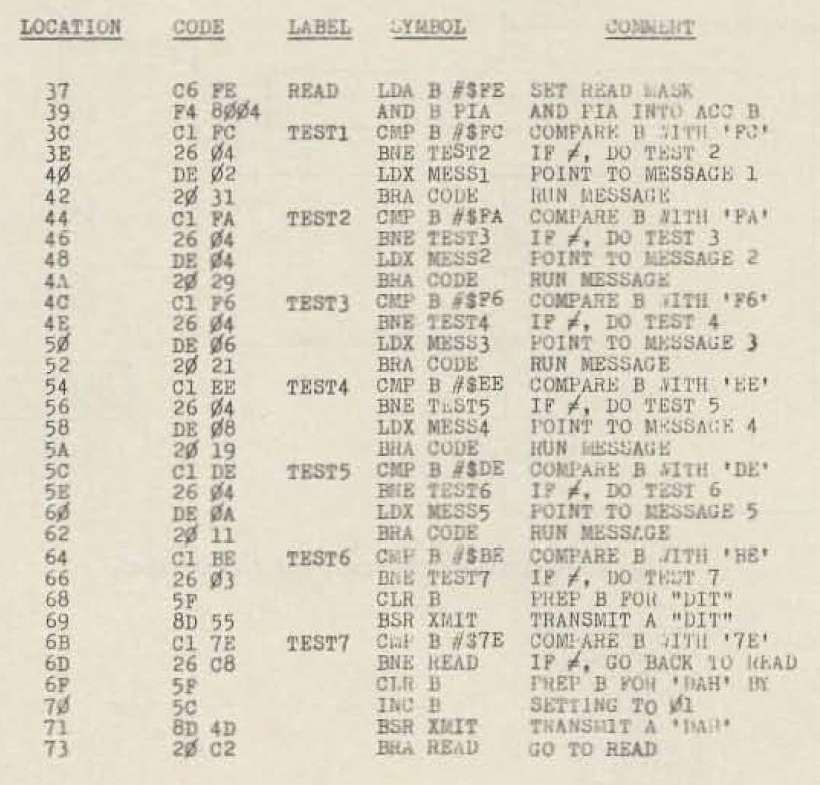
PIA Polling |
This portion of the program, illustrated in Fig. 3 and Program B, reads the input lines of the PIA (bits 1 through 7) and then sequentially compares the bit pattern with each legal pattern expected: five patterns for the five preprogrammed messages, and two for the Keyer input. If all inputs remain high, the polling routine continuously repeats the check. If a particular message is selected, however, the grounded input is detected, the index register is loaded with the starting location of the respective message text, and then a branch to "CODE" (location 0075) is executed. When the message is complete, "CODE" returns execution to the beginning of the polling routine. If the Keyer is operated, then the dot or dash contact is detected and Accumulator B is respectively cleared or set. This accumulator is then handed to the "XMIT" subroutine whose job it is to make nice clean self completing dits and dahs. After a single dit or dah, a "return from subroutine" instruction returns execution to the polling routine.
|
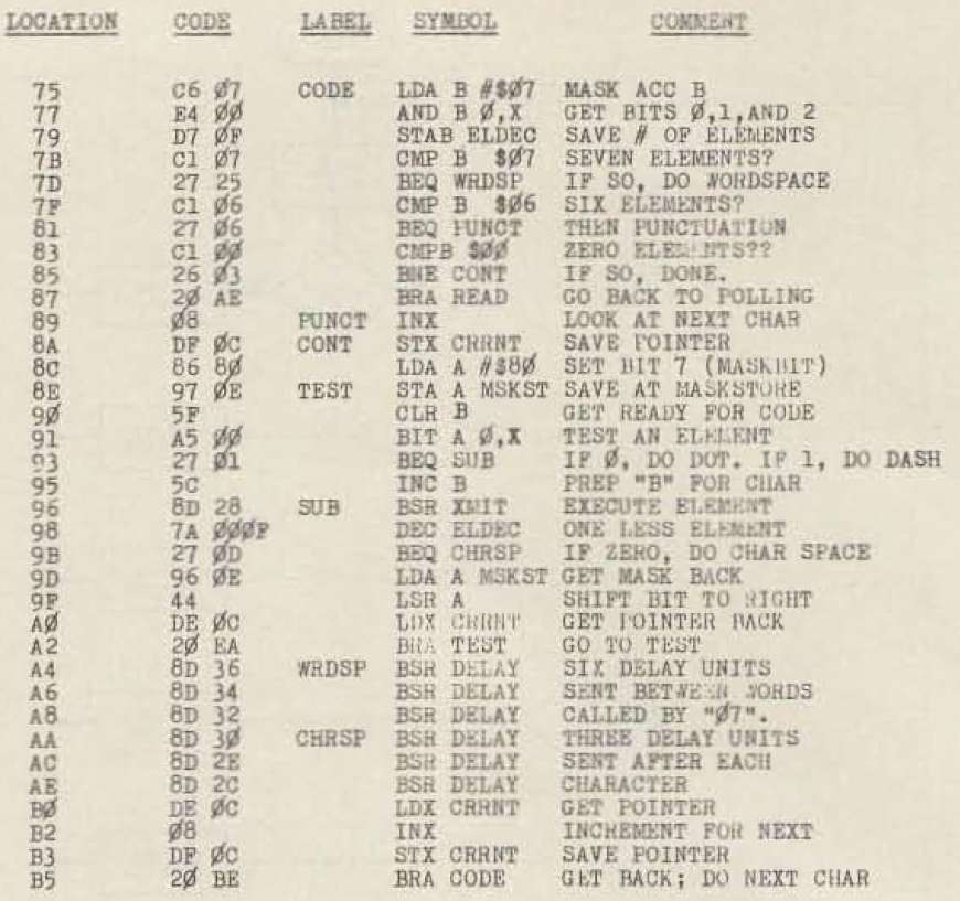
Digitizing the Morse Code |
| Fig 5A. Digitizing the Morse Code | |||||
|---|---|---|---|---|---|
| Char. | Code | Char. | Code | ||
| Char. | Binary | Hex | Char. | Binary | Hex |
| 0 | %11111 101 | $FD | N | %00000 010 | $02 |
| 1 | %01111 101 | $7D | O | %11000 011 | $E3 |
| 2 | %00111 101 | $3D | P | %01100 010 | $64 |
| 3 | %00011 101 | $1D | Q | %11010 100 | $D4 |
| 4 | %00001 101 | $0D | R | %01000 013 | $43 |
| 5 | %00000 101 | $05 | S | %00000 011 | $03 |
| 6 | %10000 101 | $85 | T | %10000 001 | $81 |
| 7 | %11000 101 | $C5 | U | %00100 011 | $23 |
| 8 | %11100 101 | $E5 | V | %00010 100 | $14 |
| 9 | %11110 101 | $F5 | W | %01100 011 | $63 |
| A | %01000 010 | $42 | X | %10110 011 | $B3 |
| B | %10000 100 | $84 | Y | %10010 100 | $94 |
| C | %10100 100 | $A4 | Z | %11000 100 | $C4 |
| D | %10000 011 | $83 | AR | %01010 101 | $55 |
| E | %00000 001 | $01 | / (Slash) | %10010 101 | $95 |
| F | %00100 100 | $24 | . (Period*) | %00000 110 | $06 |
| G | %11000 011 | $C3 | %01010101 | $54 | |
| H | %00000 100 | $04 | , (Comma*) | %00000 110 | $06 |
| I | %00000 010 | $02 | %11001100 | $CC | |
| J | %01110 100 | $74 | ? (Question*) | %00000 110 | $06 |
| K | %10100 011 | $A3 | %00110000 | $30 | |
| L | %01000 100 | $44 | Word Space | %00000 111 | $07 |
| M | %11000 010 | $C2 | Halt | %00000000 | $00 |
The real challenge, of course, was to teach the machine to speak "Morse." Essentially, the system obtains a character (a byte of data from the message text) and performs a bit test, starting at the MSB. A "1" is translated into a dash and a "0" into a dot. Knowledge of the number of dits and dahs in a particular Morse character is required in order to tell the program when to stop shifting the bit test across the data byte . This is accomplished by indicating the number of elements in the three least significant bits of the data byte. As shown in the flowchart in Fig. 4 and the listing in Program C, the A and B Accumulators a re-masked so that Accumulator B receives the number of elements . Accumulator B is then stored at "ELDEC", a memory location which is decremented every time a Morse element is completed. Fig. 5 indicates how the Morse code is encoded into the previously described format. As usual, exceptions exist, and they deserve some explanation. The format is useful for a Morse character which contains from one to five elements. Punctuation requires special handling. Therefore, if Accumulator B picks up the integer "06," then that particular byte is skipped: The six-bit character is found at the next location in the text. Two other special cases exist. One for inserting just spaces, and one for terminating the message. These situations, again detected in Accumulator B, are illustrated on the "CODE" flowchart.
I have added a column, with binary values, to the Fig 5A. Digitizing the Morse Code table above. The binary values are split into 5 Bits and 3 Bits. This was to make it a little clearer how the byte is divided. Note that the Period, Comma, and Question Mark, which take two bytes, are divided a bit differently. - K7MEM
|
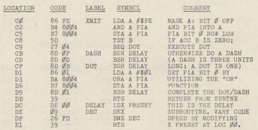
Morse Code Generation |
Subroutine XMIT (Fig. 6A/6B and Program D) handles the actual formation of, and output for, the dits and dahs. The timing for character generation is performed by a delay loop located at 00DC16. The preset value is conveniently located at 0000 (PRESET). An initial value of 170016 (588810) sets the keyer and message generator speeds at about 13 wpm. A dot consists of one unit of time of output "on" followed by an identical unit of time of output "off." A dash consists of three units of time of output "on" followed by a single unit of time of output "off". The contents of Accumulator B at the time of the call indicate the desired element (00:dot; 01:dash). The output, PIA bit 0, is cleared to assert output "on". This prevents a keydown situation during system reset.
The length of a dot, or character space, is dependent on the time it takes for the DELAY subroutine to execute. Each instruction in the DELAY subroutine requires a specific number of instruction cycles. Upon entering the DELAY subroutine, the X-Register is loaded with the value that is in location $0000. This requires 4 instruction cycles. The X-Register is then decremented in a loop, until it reaches $0000. That loop requires 8 instruction cycles, per loop. If you then multiply $170016 (588810) time 8 instruction cycles per loop, you get 47,10410 instruction cycles. If the length of an instruction cycle is 1 µs, the time for the loop is 47.104 ms. - K7MEM
|
Setup |
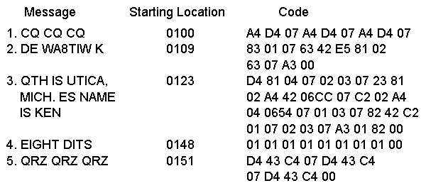
Loading the messages for the automatic sender consists of converting the text of the message into hexadecimal and storing it. (Armed with only an evaluation kit. this is a manual job!) The starting address of each message is then stored in the message vector area starting at location 0002. The current program can only support five message vectors, but there is no reason (other than memory constraints) why a multitude of messages could not be stored; simply changing a vector would then pull a new text string into the foreground. A series of "V"s or the word "test" repeated several times makes a nice brief message around which the code speed may be optimized. Fig. 7 illustrates a group of encoded messages.
|
Operation |
Start the machine by executing at 001D. The letter "K" in Morse should acknowledge start-up. At this point, the keyer may be used, or anyone of five messages may be sent by momentarily depressing the appropriate push-button. Once started, a message will proceed until completion.
The following listing is from a Cross-Assembler that I wrote in GAWK. The Cross-Assembler was running under Cygwin64 installation on a Windows 10 laptop. The "ORG" instruction at line 00129 was added to insure that the program addresses match the original listing. I'm not sure why the instruction was missing. The program would surely assemble correctly, but the addresses for the Section D and E, would not match the original assembly listing. You could make it match the original listing by padding the code with"NOP" instructions. Crude, but effective. - K7MEM
|
Multi-Memory Morse Machine Modifications - K7MEM |
The Multi-Memory Morse Machine is nice as it was designed. But there are always things that might make it better. Maybe not better, but more in line with others requirements.
The first two modifications below, go hand in hand. These modifications eliminate the Keyer Mode and increases the message capability from 5 to 7 messages. This requires a simple hardware modification and then the addition of two more messages to the message table in PROGRAM SECTION E and the message pointers in PROGRAM SECTION A. Once the changes are added, and the new messages are added, the program will need to be re-assembled. A assembly listing, with all changes added, is at the end of this section.
The third is simply a utility that eliminates the tedium of translating messages to a Hex format, that can be used by the main program.
Replace Keyer Mode with Two More Messages
As is, the Multi-Memory Morse Machine is designed to have 5 message switches and inputs for a single paddle key. This requires two inputs. One for a DOT and the other for a DASH. Along with the message switches, this uses up 7 of the 8 PIA I/O pins. The 8th I/O pin is used as an output that drives a transistor/relay keying circuit. However, I have several Keyers that are far more sophisticated than the keyer function made available in the original code. I would rather have two extra message switches than a just a simple keyer.
Changing the hardware interface is pretty straight forward. As you can see in the schematic on the right, you just eliminate the single paddle key, and its connections, and replace it with two push button switches.
Then, the code needs to be modified to intercept the two new switches and connect them to two new messages. The listing below is from Program Section B, the Input Polling Routine. Once the system is initialized, this section continuously polls the PIA input switches, 1 through 7, checking for a switch closure. Initially, the sections labeled TEST6 and TEST7 sensed the DOT and DASH switch closures from the Key Paddle. The code below now shows these sections modified to simply check the two new switches. If one is sensed, the appropriate address for the message is loaded in the Index Register, and the message is generated.
Add Message References
With the original code, messages are created at the end of the source code. The addresses, that point to the start of each message, are manually extracted and added to the definitions at the beginning of the code. Any time the messages are changed, the code needs to be re-assembled to get the start address of each message. Then the start address have to be manually updated and re-compiled. By adding the proper references, the second re-compile can be eliminated.
Message Calculator
| Message # | Message to Convert |
|---|---|
| FCB Hex Output | |
First, I will introduce the Message Calculator. It would be a simple task if the text characters related directly to a ASCII Hex value. We could use a FCC or FCB Pseudo-Op to translate the ASCII characters to their Hex value. But the Hex values we need relate to a character's Morse Code output, not ASCII. The Morse Code Hex equivalents does not resemble ASCII Hex characters at all.
The calculator above is intended to eliminate this conversion problem. There are two input areas at the top of the calculator. The one on the left is for selecting the Message Number, MSG1 through MSG7. Just select the Message Number you are working with. Then, in the area next to it, enter the message you want to be associated with that message number. Then click anywhere on the page and the message will be converted.
| Characters and Numbers | A - Z, 0 - 9 |
| Punctuation | Comma (,), Period (.), Question (?), and Slash (/) |
| Word Space | " " |
| | | AR .-.-. End of message |
| - | BT -...- Break For Text |
The Message # goes from MSG1 to MSG7. If you are not eliminating the Keyer capability, only use MSG1 to MSG5. The table on the right lists the characters that are recognized by the Message Calculator. Anything outside of that table will insert an empty entry. Valid message characters are also listed in Fig 5A. Digitizing the Morse Code.
Modified Version of the Multi-Memory Morse Machine
|
|