| Introduction |
New, high end, radios on the Amateur market have lots of bells and whistles. It's no problem connecting a RS-232 or USB cable between the radio and a computer and run a wide variety of digital modes. But not everyone has these high end radios. But even those that do, may have some older radios that would do quite well on digital modes. So this page is a description of what I did to put my IC-735 on digital modes. And, all of this can be applied to almost any older radio.
Almost any transceiver or transmitter/receiver combinations can be pressed into Digital Mode service. I have run PSK31 with my ICOM IC-735 and my Radio Shack HTX-100. And, assuming you consider CW a digital mode, I have used my Heathkit HR-1680/HX-1681 combination, which is CW only, with several different digital mode software. I also have a old Heathkit SB-101 that could be used for Digital Modes, but I have not had the inclination to do it yet. They all have the capability to be used with Digital Modes software, but in that group, only the ICOM IC-735 has Rig Control capabilities.
I mentioned Digital Modes and Rig Control earlier. Even though they both involve a central computer, they are separate items.
I will only be dealing with the PSK31. But the basic interface is the same for most of the different modes. If you want to work any of the other modes, you can find detailed explanations in many books and on-line web sites.
| Trying Digital Modes |


To operate Digital Modes properly, some hardware is required. You can purchase the hardware or build it yourself. However, you can try Digital Modes without investing any money. The drawing on the right shows a very simple setup. First you install some free Digital Modes, like Fldigi or an old free version of Ham Radio Deluxe. Then you place the computer's microphone near the radio's speaker. If you are using a laptop, the microphone is probably already built in and you just need to enable it. Then set your radio to 14.070 MHz USB and run the software. See the section on Software below.
You might think this couldn't possibly work, but it does. The computer's microphone has plenty of sensitivity to pick up the output from the radio. The sound may be a little noisy, but usable. In fact, it will probably pick up much more than you want. Every noise in your shack will be picked up, like the dog barking. But the point is, all Digital Mode software has a waterfall window, which is a continuous scan of the audio from the radio.
| PSK31 Frequencies | |||
|---|---|---|---|
| Frequency | Amateur Band | Frequency | Amateur Band |
| 1.838 MHz | 160 meter | 24.920 MHz | 12 meter |
| 3.580 MHz | 80 meter | 28.120 MHz | 10 meter |
| 7.035 MHz* 7.070 MHz* |
40 meter (region 3) 40 meter (regions 1,2) |
50.290 MHz | 6 meter |
| 144.144 MHz | 2 meter | ||
| 10.142 MHz | 30 meter | 222.07 MHz | 1.25 meter |
| 14.070 MHz | 20 meter | 432.2 MHz | 70 centimeter |
| 18.100 MHz | 17 meter | 909 MHz | 33 centimeter |
| 21.080 MHz** | 15 meter | ||
|
* IARU Region 1
includes the member societies representing amateur radio operators in Africa, Europe, the Middle East, and northern Asia. * IARU Region 2 includes the member societies representing amateur radio operators in Americas (North and South America). * IARU Region 3 includes member societies representing amateur radio operators in Australia, most of Asia, and the Pacific Islands. ** Current usage as of 2010, based on observation, is centered on 7,070.150 KHz and 21,070.150 KHz. 7,035.150 KHz is commonly used in Region 2 as of 2012. There is no authoritative list, as the frequencies are determined by common convention. |
|||
At 14.070 MHz most of the signals you see will be PSK. If you select one of those signals with your mouse, you should see the decode in a upper window. Any noise in the shack might cause the decoding to be a little sporadic, but it will work.
The drawing also shows a speaker from the computer placed close to the radio's microphone. You could use this for transmitting, but I would not recommend it. Again, your radio's microphone, like the computer's microphone, will be picking up every noise in the shack. The extra noises might be acceptable, and even expected, when your operating SSB Phone, but these noises have no place in the Digital Mode segment. Those noises will make your signal unnecessarily wide and interfere with other communications.
| Audio/PTT/CW Interface |
I made my interface many years ago, before commercial interfaces were readily available. I think the hot operating system of the time was Windows XP, and there wasn't a problem getting the USB to Serial Port converter cables working. My goodness, how things have changed. But, in spite of those changes, this interface still works fine.
The IC-735 is a relatively old transceiver, but it is still very popular. For Digital Modes it has a connector on the rear panel, ACC(1), that provides access to the Audio Input/Output and PTT. The only drawback that I have found, with using the rear connector, is that, the Audio Input bypasses the VOX. If the VOX was available, I wouldn't need to include some circuitry that enables the PTT and avoid any issues with USB to Serial Port converter cables. But, after using it for a while, I actually prefer it this way. And, since the levels for PTT are the same for CW Keying, I can get a bonus mode.
Initially, all I knew was that I needed to get the audio from my radio to my computer and the audio from my computer to my radio. So I bought a small spool of shielded audio cable and some connectors and then wired the computer audio's to the radio's audio. At the time, my computer was a HP G62 Laptop. The laptop had separate Audio Input and Audio Output connectors. Later on I used this same interface on a newer laptop that had a single 4-Position combo audio jack for audio in and out. To resolve the issue, I found a P318‑06N‑MFF 4‑Position to 3‑Position Audio Adapter cable made by Tripp‑Lite. The adapter cable provides two connectors allowing me to just plug in the existing audio cables.
Making the computer enable the PTT or CW Key input took a little more work. All of the available Digital Mode software has the capability to use a Serial Port to enable the PTT. Some of the software, even include CW Keying via that same port. An exception to that is FlDigi. Although, you can build a circuit that will take the audio tone from FlDigi, rectify and filter it, and use it to key CW directly. See the FlDigi web site for more information. If your computer has a built in Serial Port, part of the work is done. However, most laptops have done away with Serial Ports and only includes USB Ports. So, since my laptop didn't have a built in Serial Port, I bought a USB to Serial Port converter cable. I initially bought one with a DB25 RS-232 connector, but later replaced the USB to Serial Port converter cable with a DB9 RS-232 connector. The schematic reflects the DB9 connections.
| RS-232 Control Signal Voltage Level | State |
|---|---|
| -3 to -25 Volts | Off (0) |
| +3 to +25 Volts | On (1) |
That gave me some control signals that I could use for enabling the CW Keying/PTT. But there were two issues. The signal lines, as shown in the chart, can be any where between -3 and -12 volts with inactive (logic 0) and between +3 and +12 volts when active (logic 1). And, the CW Keying/PTT input lines on the radio requires a signal that is Active Low.
The circuit above solves these problems. I built the circuit right into the plastic shell used to house the mating RS-232 DB9 connector. When one of the RS-232 Signal lines is activated (CTS | DSR = +3 to +12V), the transistor is saturated and conducts any voltage on the collector ground. This is sufficient to put the radio into transmit (PTT), or operate the CW Keying input. The diode and resistor (D1-R1, D2-R2) provides protection for the transistor at this time. When the Signal lines is inactive active (CTS | DSR = −3 to −12V), the diode and resistor (D1-R1, D2-R2) keeps any high negative voltage excursions from destroying the transistor.
| Rigblaster Nomic Audio/PTT/CW Interface |
Years ago, I picked up a Rigblaster Nomic interface (NIB) at a ham fest. The original owner bought it, but then decided to use something else for an interface. The box contained everything you should need for connecting your computer, through microphone, to your radio. While I had been using the Simple Interface, detailed above, I thought that the Nomic might be a little cleaner and easier to use. And, it had some isolation between the computer and the radio.
The only problems I had with the parts supplied was that, my dog ate the CD and it was a long time between buying it and using it. Yes, my dog really did eat the CD. Of course, that was my fault for leaving it where he could get at it. The time issue had to do with the USB to Serial Port Converter cable. The cable would have worked great, if I used it when my computer was running Windows XP, Windows 7, or Windows 10. However, now I have Windows 11. The cable was a early Prolific based cable and is no longer supported in Windows 11. But that's OK because I just purchased new USB to Serial Port Converter cables that are FTDI based.
The Nomic really only manages two functions. One, the Nomic generates a PTT signal from the RS-232 connector (J3). Secondly, the Nomic routes computer audio to the radio. Generally, a USB to RS-232 Serial Port Converter cable is used on the computer to create a RS-232 Serial Port for the PTT circuitry. Referencing the schematic above:
- The PTT signal line in a radio normally sits at a positive voltage. The exact voltage depends on the radio, but is generally in the range of 8 to 12 Volts. When pulled to ground, the radio transitions from the receive mode to the transmit mode. The Nomic uses the DTR and RTS signals from J3 to generate the PTT signal. When the RS-232 Serial Port is configured on the compute, the DTR and RTS signals are at ground potential (0). When the computer generates a PTT signal, the DTR and RTS signals go high (1) and forward bias the diodes D1 and D2. These diodes form a OR gate, which then drives the LED in U1, the Opto-Isolator. The transistor in the Opto-Isolator is then used as a switch to turn the PTT signal to ground. When DTR and RTS return low again, the PTT is released.
- Audio is routed from the computer to J4 of the Nomic using a 3-wire shielded cable (stereo). These two audio channels are then mixed via R3 and R4 and applied to the primary of T1. Capacitor C3, along with R3 and R4, form a low pass filter. The transformer is used to isolate the computer audio from the radio's audio. VR1 is then used to adjust the audio level into the radio. Many radios have a positive voltage on the audio input to power electret microphones. Capacitor C1 is used to isolate the audio from T1 and VR1 should a voltage exist.
J5 is just a straight through connection from J4. If you normally use headphones or external speakers, J5 can be used.
Over the years, computer peripheral access has changed. Computers use to have DB-9 RS-232 connectors for a Serial Port. You might find one on a desktop these days, but laptops have replaced it with USB ports. Now, if you need a Serial Port, you get a USB to RS-232 Serial Port Converter cable. Another change is the Audio In/Out jack(s). There use to be 1/8" (3.5mm) two stereo jacks. One for Audio Input (Microphone) and another for Audio Output (headphones). Now there is only a single jack that contains both. The Audio Input (Microphone) is no longer stereo.
If you had a pair of headphones or ear buds, you can still plug them directly into the newer jacks. However, if you need to use both the input and output capabilities, you might want to get a splitter cable. The schematic on the right shows the wiring for a splitter cable. Although not shown, the connections from P1 to J1/J2 should be shielded cable. The splitter that I have is only about 6" in length and doesn't seem to be affected by any interference.
Connecting the Nomic to a transceiver
The drawing below shows how you might connect your computer to a radio, using the Nomic. Specifically, the compute is new, in that, only a single TRRS jack is used for Audio In and Audio Out. The Y-Adapter separates the Audio In and Audio Out. Should you have an an older computer with a separate jack for audio input and output, the Y-Adapter should not be needed. The Y-Adapter is only 6" in length.
Cable lengths depend on your particular installation and available lengths. I just used whatever cable that I had on hand. The USB to RS-232 Converter Cable was 6' in length. It can be purchased with a 3' length. The Stereo Patch Cable, which came with the Nomic, was also 6' in length. For the Mono Patch Cable, I actually used a 6' Stereo Patch Cable with a Stereo to Mono Adapter. The Mic Cable was included with the Nomic and was 3' in length.
| ICOM IC-735 Baud Rate |
| IC-735 Baud Rates | ||
|---|---|---|
| DB4 | DB5 | Baud Rate |
| 0 | 0 | --- |
| 1 | 0 | 9600 |
| 0 | 1 | 1200* |
| 1 | 1 | 300 |
| * Factory setting and standard CI-V baud rate. | ||
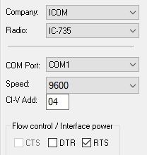
The IC-735 comes factory preset for 1200 Baud and the network address is "4". 300 and 9600 baud communication speeds are also available. Each transceiver connected to the ICOM CI-V System requires its own unique network address.
Changing the baud rate is relatively simple, but you do need to exercise caution. On the right are several small images. They are intended to help locate the jumper area. Clicking on the images will open up a bigger version of the image.
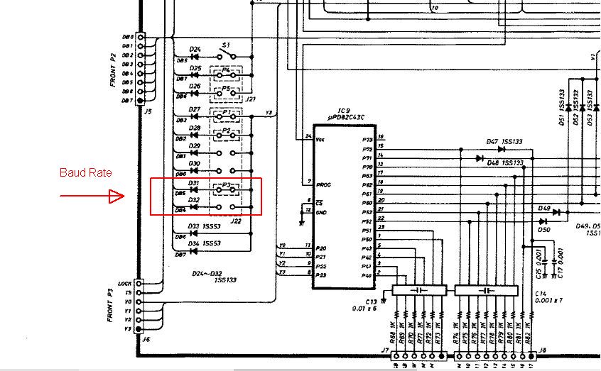
Just for clarity, click on the image labeled Schematic. The two jumper areas (DB4 and DB5) are boxed in red. The jumper, P3, is shown in the DB5 position. The DB4 position shows no jumper. This is the correct jumper positioning for 300 baud.
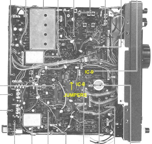
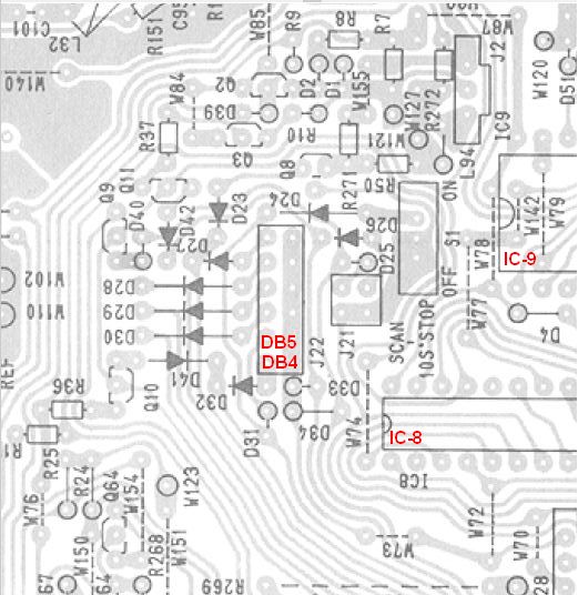
The Schematic makes it pretty clear, but finding the area in the IC-735 can be difficult. Start by clicking on the image labeled Bottom View. This is a image of the bottom of the IC-735, with the cover removed. Highlighted are IC-9 and IC-8, just to the left of the battery. On the left of IC-8 is the jumper area. Once you have located this area in your IC-735 refer to the image marked Physical. This shows in greater detail, where the DB4 and DB5 jumper exist.
So, in the end, to change the baud rate from 300 baud to 9600 baud, carefully remove the jumper P3 from the DB5 position and insert it into the DB4 position.
| Rig Control with a ICOM IC-735 |
The drawing below is the interface I used to go from a computer's RS-232 communication port to the ICOM Remote Control Jack (CI-V). I included a section of the IC-735 input circuitry. Its only meant to give you an idea of the circuitry that is being driven, so it is a little incomplete. The IC-735 input circuitry directly drives the IC-735 Microcontroller (U6 - HC63A01V1C80).
Note: There is a discrepancy in the IC-735 Service Manual on the value of R42. The parts list has R42 listed as being 100K Ω, but the sketch in Section 16 - ICOM CI-V Communication Interface System shows that same resistor as being 10K Ω.
The best I can tell is that the interface design is attributed to Nigel Thompson, KG7SG, and appeared in the 7/92 issue of QST. But if you look around the internet, you can find a dozen other interfaces that will do the job. In fact, now you can now find a CI-V interface cable that plugs directly into a USB port and goes directly to the CI-V input port. Like the Icom CT-17 USB FTDI Chipset CI-V Cat Control Programming Cable 3 Feet. Note that this cable will work with my IC-735, because it has a "mono" 3.5mm phone plug at the end. Some Icom radios require a "stereo" 3.5mm phone plug. Check your radio manual to be sure you get the right one for your radio.
| RS-232 Signal | State |
|---|---|
| -3 to -25 Volts | 1 |
| +3 to +25 Volts | 0 |
| RS-232 Control | State |
| -3 to -25 Volts | Off |
| +3 to +25 Volts | On |
| CI-V Signal | State |
| > 2.0 Volts | 1 |
| < 0.8 Volts | 0 |
| DTE Signal Source "Computer End" | ||
|---|---|---|
| DB25 | DB9 | Signal |
| 8 | 1 | DCD |
| 3 | 2 | RXD |
| 2 | 3 | TXD |
| 20 | 4 | DTR |
| 7 | 5 | GND |
| 6 | 6 | DSR |
| 4 | 7 | RTS |
| 5 | 8 | CTS |
| 22 | 9 | RI |
I have seen this design in many places on the internet. But they usually just show the diagram, without any explanation. Often the orientation of some of the parts is not clear. I hope the following explanation helps.
The intent of this interface is to convert the Uni-Directional RS-232 Rx/Tx signals to the Bi-Directional ICOM CI-V Rx/Tx signal. The RS-232 signal and control lines switch from a positive to a negative voltage. Whereas the ICOM CI-V is Bi-Directional and switches between ground (< 0.8 Volts) and some positive voltage (> 2.0 Volts). When no data is being received from the computer, and no data is being sent to the computer, the ICOM CI-V line rests at a positive voltage.
The RS-232 TxD signal line (DB9 - Pin 2) is routed through resistor R8 and transistor Q4 to the Icom CI-V input connector. The diode, D3, protects Q4 from high negative voltages.
For RXD, data from the Icom CI-V output connector, is routed through Q3 and Q2. Q1 is then used to switch the RS-232 RxD signal line (DB9 - Pin 3) between a positive to negative voltage.
The computer's RS-232 Control Signal, RTS, provides positive power, through D1. RTS is wrapped back to the computer's CTS and DSR RS-232 Control Signals. Make sure the RTS is turned on when configuring the CI-V RS-232 Control Port.
While it may look like an error, the orientation of C1 is correct. The interface uses the computer's TXD signal line to create negative voltage for the interface. Negative excursions of the TXD signal are routed though diode D2 and stored in capacitor C1. This provides the negative voltage required for the RXD signal line, through R1.
| Software |
My needs for digital modes with the IC-735 are pretty simple. I want to use Rig Control and operate PSK-31, CW, and possibly RTTY. For me, an old free version of Ham Radio Deluxe (HRD) fits the bill. Specifically, I use Version 5.24.38. The old free versions of HRD are not readily available on-line any more, but I have several of them archived, from a time when they were available.

HRD is a suite of utilities that can handle Rig Control, Digital Mode Decode/Encode, Contact Logging, Antenna Positioning, etc.. The two pieces of HRD that I use are Ham Radio Deluxe (HRD) for Rig Control and Digital Master 780 (DM780) for Digital Mode Decode/Encode. So my setup is pretty simple.
The drawing on the right gives a good idea of the interconnect needed for operating digital modes. At the top are the HRD and DM780 processes (Green) that are running on the computer. They communicate with each other and connect to the hardware interfaces (Pink) through two COM ports (COM1 and COM4).
The HRD process uses COM1, which on my computer is a "real" RS232 interface. The DB9 connector for that port is on the rear panel. RXD and TXD communicate with the IC-735 via the RS-232 to CI-V interface. RTS is used to power the interface.
The DM780 process uses COM4 to provide PTT and CW Keying. RTS drives the PTT interface and DTR drives CW Keying. DM780 also manages the audio between the computer and the IC-735.
HRD Configuration
When you first install and start up HRD, the Connect option window will come up, allowing you to initially set up the HRD communication. After that, each time you start HRD, the process will automatically connect to your radio using the saved options. The Connect option area can be accessed at any time, to modify the communication parameters. The IC-735 interface can operate at 300, 1200, or 9600 Baud. The factory default is 1200 Baud. A jumper on the Main circuit board must be changed for the other speeds.
Note: For the communication to operate on startup, the interface and cables must be connected and the radio must be powered up. Otherwise, the connection will fail. Communication can then be established, once everything is connected and powered up, using the Connect option.
Before you dismiss the Connect window, using the Connect button, check the boxes at the bottom that are appropriate to your setup. For my setup I check "Always connect to this radio when starting HRD" and "Start Digital Master 780". With this setup, each time I start HRD the computer will connect to my radio, start the radio display, and then start DM780.
DM780 Configuration
When DM780 starts up, use the Program Options button to bring up the Program Options window. From this window we need to set up PTT, Modes+IDs, Radio, and Soundcard. These should get you started. The other options may need to be adjusted later.
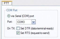
The PTT setup defines how you want your radio keyed. In my case I want the PTT output enabled "via Serial COM Port". While the picture shows COM3, I actually selected COM4. On this port I want RTS to be enabled, to key the radio.
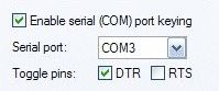
Next, select Mode+IDs to define the port and signal for CW keying. In my case, I use the same port that PTT is defined
RTS drives the PTT interface and DTR drives CW Keying. These signals are set in the DM780 ‑> Program Options ‑> PTT and DM780 ‑> Program Options ‑> Mode+IDs area. The interface for each of these signals is a single transistor with a series resistor and parallel diode on the base.
DM780 is also used to manage the computer's Audio In and Audio Out. Note that the drawing shows the PTT, Audio In, and Audio Out use the ACC(1) connector on the rear of the IC-735. Because the Audio In, and Audio Out on the IC-735 are capacitor coupled, the audio wires are just two shielded audio cables. Some may use transformer coupling, to help prevent ground loops. But I have not had any issues with ground loops.
| My Shack Computer for Digital Modes |
To operate any of the Digital Modes, like PSK32/64/128, you need a radio that has Upper Sideband (USB) capability and a computer with Digital Mode software. The audio output (speaker) from the radio is routed to the computer (Audio In or Microphone) and the audio output from the computer is routed to the radio's audio input. This can simply be done using the radio's Microphone connector and the Speaker output.
I use a pretty old computer in my shack. It is a Compaq Presario SR1230NX desktop running Windows XP. I would have preferred something that runs Windows 10, but the OS on the Compaq is not upgradable, because the chip set is too old. The computer suffered a voltage spike, during a storm, that damaged the LAN Ethernet input. A WiFi PCI adapter board was added for network/internet access. The following is a short list of the specifications for the Compaq Presario SR1230NX.
The table below is a short list of the specifications for the Compaq Presario SR1230NX. And there are two sketches (Front and Rear Panel) to help show the available I/O ports. Although not shown, there are four expansion slots on the rear of the computer, 1- Accelerated Graphics Port (AGP) and 3 - Peripheral Component Interconnect (PCI).


- Processor/Chipset: CPU AMD Athlon XP 3200+ / 2.2 GHz, Data Bus Speed 400 MHz
- Memory: 1 GB (Physical Limitation)
- Hard Drive: Capacity 160 GB,Interface Class Parallel ATA, Interface Type IDE
- Optical Storage (1st): Drive Type DVD-Writer, Type DVD+RW (+R DL), Interface Type IDE
- Optical Storage (2nd): Type CD-ROM,Read Speed 48x,Drive Type CD-ROM
- Front Panel
- Serial Data Ports: 3 - USB 2.0 (COM 4, 5, 6), 1 - Firewire (IEEE 1394) port
- Audio Ports: Audio In, Microphone, Headphone (All Stereo)
- Card Reader: Type 9 in 1 card reader
- Rear Panel
- Serial Ports: 4 - USB 2.0 (COM 7, 8, 9, 10), 1 - Firewire (IEEE 1394) port, 1 - RS-232 Serial Port (DB9)
- Audio Ports: Microphone, Audio Line-Out, Audio Line-In (All Stereo)
- Comm Ports: LAN Ethernet (Broken)
- Peripherials: PS2 Mouse, PS2 Keyboard, VGA Monitor, Printer Port (DB25)
- Rear Expansion Slots - 3 PCI & 1 AGP Bay
- AGP: Available
- PCI: Composit Video, S-Video
- PCI: WiFi PCI Adapter
- PCI: Modem (Line In RJ-11)
I could have loaded some flavor of Linux. I have over 30 years of experience installing and managing Unix systems. But if I installed Linux, I would lose a lot of the machine's utility. There is a lot of Audio/Video utility to the Compaq, which I do use, that would be useless under Linux. Plus, going to Linux limits the availability of ham based software. I know that I could run some of the software in a Virtual Machine (VM) like Wine, but that just over complicates things.
Over a period of about 2 months, I ran through a series of tests, using various versions of Linux, but didn't like any of them. The OSs were too varied and they were too limited in the hardware and software that they support. I finally went back and reinstalled the original XP operating system.