| Introduction |
| Color Name | HEX | Color | Color Name | HEX | Color |
| Pastel Red | #FF6961 | Pastel Red | Dark Pastel Red | #C23B22 | Dark Pastel Red |
| Pastel Green | #77DD77 | Pastel Green | Dark Pastel Green | #03C03C | Dark Pastel Green |
| Pastel Blue | #AEC6CF | Pastel Blue | Dark Pastel Blue | #779ECB | Dark Pastel Blue |
| Pastel Magenta | #F49AC2 | Pastel Magenta | Pastel Violet | #CB99C9 | Pastel Violet |
| Pastel Pink | #DEA5A4 | Pastel Pink | Pastel Pink 2 | #FFD1DC | Pastel Pink 2 |
| Pastel Gray | #CFCFC4 | Pastel Gray | Light Pastel Purple | #B19CD9 | Light Pastel Purple |
| Pastel Orange | #FFB347 | Pastel Orange | Pastel Yellow | #FDFD96 | Pastel Yellow |
| Pastel Brown | #836953 | Pastel Brown |
| Process Start/End Point |
Description: The symbol is used to mark the starting point or ending point of the system.
| Parameter | Description | Example | |
|---|---|---|---|
| Lib_FC_Dwg_Obj | jsGraphics Object that points to the drawing. | ||
| Lib_FC_Name | Name of Starting process. | ||
| Lib_FC_Start_X, Lib_FC_Start_Y | Center of FC Object. Object will be 120 pixels wide and 20 pixels high. |
Show/Hide Grid (10x10), Center Mark, Pins (green dot). |
|
Return: The X and Y connection point pairs are returned for the top-center, right-center, bottom-center, and left-center, respectively.
Usage: The selections from the table above, are used to create the example below. After selecting and entering your specific information, the example can be used directly, with a copy/paste. The items in Red are the only ones that need to be adjusted to your specific needs. The lines in Green are just comments and can be deleted. Due to space limitations, some of the lines below may be split onto more than one line.
| Action or Process Symbol |
Description: Represents a single step, or an entire sub-process within a larger process.
| Parameter | Description | Example | |
|---|---|---|---|
| Lib_FC_Dwg_Obj | jsGraphics Object that points to the drawing. | ||
| Lib_FC_Info | Array that contains the number of lines to be displayed within the Proc symbol, followed by
the text for each of the lines. Example: P1_Info = [ 3, "This is", "a Test", "Symbol" ];
An optional ID can be added to the end of the array for identifying the process in your
code. The ID will be located at the upper right of the symbol.P1_Info = [ 3, "This is", "a Test", "Symbol", "P1" ]; |
||
| Lib_FC_Center_X, Lib_FC_Center_Y | Center of FC Object.
Object will be 120 pixels wide and 25, 40, or 55 pixels high, depending on whether there is 1, 2 or 3 lines of Info. |
Show/Hide Grid (10x10), Center Mark, Pins (green dot). |
|
Return: Returns the X and Y connection point pairs are returned for the top-center, right-center, bottom-center, and left-center, respectively.
Usage: The sample function call is shown below. The sample draws a Process rectangle and places a three line label, "This is", "a Test", "Symbol" in the center. Because 3 lines are defined, the vertical size is increased to 55 pixels to accomodate the text. A Process ID (P1) is placed outside the symbol, on the upper right side.
| Decision Symbol |
Description: A decision or branching point. Lines representing different decisions emerge from different points of the diamond.
| Parameter | Description | Example | |
|---|---|---|---|
| Lib_FC_Dwg_Obj | jsGraphics Object that points to the drawing. | ||
| Lib_FC_Info | Array that contains the text for the points of the decision diamond. The order of
of the information is shown below. The ordering is Question[0],
Label_Top[1], Label_Rt[2],
Label_Bot[3], and Label_Lt[4]. D1_Info = [ "Test A",
"In", "A > 0",
"A = 0", "A < 0" ];
An optional ID can be added to the end of the array for identifying the process in your
code. The ID will be located at the upper right of the symbol.D1_Info = [ "Test A",
"In", "A > 0",
"A = 0", "A < 0", "D1" ];
|
||
| Lib_FC_Start_X, Lib_FC_Start_Y | Center of FC Object. Object will be 80 pixels wide and 60 pixels high. Only one line of Info (Info[0]) allowed |
Connector Points |
|
Return: The return array contains the coordinates for each of the diamond points. The ordering of the points are Top_X, Top_Y, Right_X, Right_Y, Bottom_X, Bottom_Y, Left_X, Left_Y.
Usage: The sample function call is shown below. The sample draws a Decision diamond and places a label, "Test A", in the center. It also places the label "A < 0" on the left point, "A > 0" on the right point, and "A = 0" on the bottom point. A Decision ID (D1) is placed outside the symbol, on the upper right side.
D1_XY_Return = [D1_Top_X, D1_Top_Y, D1_Rt_X, D1_Rt_Y, D1_Bot_X, D1_Bot_Y, D1_Lt_X, D1_Lt_Y] = Decision( Lib_FC_Dwg_Obj, D1_Info, D1_Start_X, D1_Start_Y );
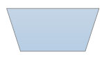
| Input/Output Symbol |
Description: Represents material or information entering or leaving the system, such as customer order (input) or a product (output). Allows for multiple lines of text.
| Parameter | Description | Example | |
|---|---|---|---|
| Lib_FC_Dwg_Obj | jsGraphics Object that points to the drawing. | ||
| Lib_FC_Info | Array that contains the number of lines to be displayed within the InOut symbol, followed by
the text for each of the lines. Example: IO1_Info = [ 3, "This is a test of", "the Input/Output", "Symbol" ];
An optional ID can be added to the end of the array for identifying the process in your
code. The ID will be located at the upper right of the symbol.IO1_Info = [ 3, "This is a test of", "the Input/Output", "Symbol", "IO1" ]; |
||
| Lib_FC_Start_X, Lib_FC_Start_Y | Center of FC Object. Object will be 120 pixels wide and 25, 40, or 55 pixels high, depending on whether there is 1, 2 or 3 lines of Info. |
Connector Points |
|
Return: The X and Y connection points returned for the top-center, right-center, bottom-center, and left-center, respectively
Usage: The sample function call is shown below. The sample draws a Process rectangle and places a three line label, "This is", "a Test", in the center. Because 3 lines are defined, the vertical size is increased to 55 pixels to accomodate the text. A Process ID (P1) is placed outside the symbol, on the upper right side.
IO1_Return_XY = [IO1_Top_X, IO1_Top_Y, IO1_Rt_X, IO1_Rt_Y, IO1_Bot_X, IO1_Bot_Y, IO1_I_Lt_X, IO1_Lt_Y] = InOut( Lib_FC_Dwg_Obj, IO1_Info, IO1_Start_X, IO1_Start_Y );
| Off Page Symbol |
Description: Indicates that the process continues off page.
| Parameter | Description | Example | |
|---|---|---|---|
| Lib_FC_Dwg_Obj | jsGraphics Object that points to the drawing. | ||
| Lib_FC_Info | Array that contains, in order, the Direction,
Source/Destination Information, and Symbol
Size Increase. The default symbol size is 40x40 pixels.
The Symbol Size Increase defines the overall increase in X and Y. Example: OP1_Info = [ "Right", P1-C7, 0 ]; - will produce a Off Page symbol facing right, with the label "P1_C1" inside, and it will be 40x40 Pixels. OP1_Info = [ "left", P1-C7, 10 ]; - will produce a Off Page symbol facing left, with the label "P1_C1" inside, and it will be 50x50 Pixels. |
Direction Src/Dest Size |
|
| Lib_FC_Start_X, Lib_FC_Start_Y | Center of FC Object. | Connector Points |
|
Return: The X and Y coordinates of the input and output are returned in an array.
Usage: The sample function call is shown below.
OP1_XY_Return = [OP1_In_X, OP1_In_Y, OP1_Out_X, OP1_Out_Y] = OffPage( Lib_FC_Dwg_Obj, OP1_Info, OP1_Start_X, OP1_Start_Y );
| Manual Input Symbol |
Description: Represents a step where a user is prompted to enter information manually.
| Parameter | Description | Example | |
|---|---|---|---|
| Lib_FC_Dwg_Obj | jsGraphics Object that points to the drawing. | ||
| Lib_FC_Info | Array that contains the number of lines to be displayed within the InOut symbol, followed by
the text for each of the lines. Example: IO1_Info = [ 3, "Input your", "Name", "?" ];
An optional ID can be added to the end of the array for identifying the process in your
code. The ID will be located at the upper right of the symbol.IO1_Info = [ 3, "Input your", "Name", "?", "MI1" ]; |
||
| Lib_FC_Start_X, Lib_FC_Start_Y | Center of FC Object. Object will be 80 pixels wide and 25, 40, or 55 pixels high, depending on whether there is 1, 2 or 3 lines of Info. |
Connector Points |
|
Return:
Usage: The sample function call is shown below.
MI1_Return_XY = [MI1_Top_X, MI1_Top_Y, MI1_Rt_X, MI1_Rt_Y, MI1_Bot_X, MI1_Bot_Y, MI1_Lt_X, MI1_Lt_Y] = ManInput( Lib_FC_Dwg_Obj, MI1_Info, MI1_Start_X, MI1_Start_Y );
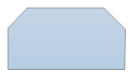
| Preparation Symbol |
Description: Represents a set-up to another step in the process.
| Parameter | Description | Example | |
|---|---|---|---|
| Lib_FC_Dwg_Obj | jsGraphics Object that points to the drawing. | ||
| Lib_FC_Info | Array that contains three lines of text, plus a optional ID. The three lines of text
are separate array entries. If the optional ID is not required, enter it as "". Example: PR1_Info = [ Test, "Preparation", "Symbol", "PR1"];
|
||
| Lib_FC_Start_X, Lib_FC_Start_Y | Center of FC Object. | Connector Points |
|
Return: The X and Y connection points returned for the top-center, right-center, bottom-center, and left-center, respectively. See the usage example below.
Usage: The sample function call is shown below.
PR1_Info = [ Test, "Preparation", "Symbol", "PR1"];
PR1_Return_XY = [PR1_Top_X, PR1_Top_Y, PR1_Rt_X, PR1_Rt_Y, PR1_Bot_X, PR1_Bot_Y, PR1_I_Lt_X, PR1_Lt_Y] = Preperation( Lib_FC_Dwg_Obj, PR1_Info, PR1_Start_X, PR1_Start_Y );
| Connector Symbol |
Description: Indicates that the flow continues where a matching symbol (containing the same letter) has been placed.
| Parameter | Description | Example | |
|---|---|---|---|
| Lib_FC_Dwg_Obj | jsGraphics Object that points to the drawing. | ||
| Lib_FC_Info | Array that contains one or two text fields. The first field should be a letter
that will match another connector, somewhere else on the page. The second field can be a
zone reference to make finding it easier. The first field will be in a larger font than
the second (zone) field. Example: Con1_Info = [ A, "C5"]; |
||
| Lib_FC_Start_X, Lib_FC_Start_Y | Center of FC Object. | Connector Points |
|
Return: The X and Y connection points returned for the top-center, right-center, bottom-center, and left-center, respectively
Usage: The sample function call is shown below.
Con1_Return_XY = [Con1_Top_X, Con1_Top_Y, Con1_Rt_X, Con1_Rt_Y, Con1_Bot_X, Con1_Bot_Y, Con1_I_Lt_X, Con1_Lt_Y] = Connector( Lib_FC_Dwg_Obj, Con1_Info, Con1_Start_X, Con1_Start_Y );
| Or Symbol |
Description: Indicates that the process flow continues in more than two branches. No text information is associated with this symbol.
| Parameter | Description | Example | |
|---|---|---|---|
| Lib_FC_Dwg_Obj | jsGraphics Object that points to the drawing. | ||
| Lib_FC_Start_X, Lib_FC_Start_Y | Center of FC Object. | Connector Points |
|
Return: The X and Y connection points returned for the top-center, right-center, bottom-center, and left-center, respectively
Usage: The sample function call is shown below.
OR1_Return_XY = [OR1_Top_X, OR1_Top_Y, OR1_Rt_X, OR1_Rt_Y, OR1_Bot_X, OR1_Bot_Y, OR1_I_Lt_X, OR1_Lt_Y] = Or_Sym( Lib_FC_Dwg_Obj, OR1_Width, OR1_Height, OR1_Start_X, OR1_Start_Y );
| Summoning Junction Symbol |
Description: Indicates a point in the flowchart where multiple branches converge back into a single process.
| Parameter | Description | Example | |
|---|---|---|---|
| Lib_FC_Dwg_Obj | jsGraphics Object that points to the drawing. | ||
| Lib_FC_Start_X, Lib_FC_Start_Y | Center of FC Object. Object will be 80 pixels wide and 25, 40, or 55 pixels high, depending on whether there is 1, 2 or 3 lines of Info. |
Connector Points |
|
Return: The X and Y connection point pairs are returned for the top-center, right-center, bottom-center, and left-center, respectively.
Usage: The sample function call is shown below.
SJ1_Return_XY = [SJ1_Top_X, SJ1_Top_Y, SJ1_Rt_X, SJ1_Rt_Y, SJ1_Bot_X, SJ1_Bot_Y, SJ1_I_Lt_X, SJ1_Lt_Y] = Sum_Junct( Lib_FC_Dwg_Obj, IO1_Info, IO1_Width, IO1_Height, IO1_Start_X, IO1_Start_Y );
| Merge Symbol |
Description: Indicates a step where two or more sub-lists or sub-processes become one.
| Parameter | Description | Example | |
|---|---|---|---|
| Lib_FC_Dwg_Obj | jsGraphics Object that points to the drawing. | ||
| Lib_FC_Subs | Specifies the sub-lists or sub-processes being merged. Limit is 4. Any more than that would make it too wide. |
||
| Lib_FC_ID | Specifies the Merge ID. | ||
| Lib_FC_Start_X, Lib_FC_Start_Y | Center of FC Object. | Connector Points |
|
Return: The X and Y connection points returned for the top-center, right-center, bottom-center, and left-center, respectively
Usage: The sample function call is shown below.
M1_Return_XY = [M1_Top_X, M1_Top_Y, M1_Rt_X, M1__Rt_Y, M1_Bot_X, M1_Bot_Y, M1_Lt_X, M1_Lt_Y] = Merge( Lib_FC_Dwg_Obj, M1_Subs, M1_ID, M1_Start_X, M1_Start_Y );
| Collate Symbol |
Description: Indicates a step that orders information into a standard format.
| Parameter | Description | Example | |
|---|---|---|---|
| Lib_FC_Dwg_Obj | jsGraphics Object that points to the drawing. | ||
| Lib_FC_Format | Specifies the name of the format that the data is being collated to. | ||
| Lib_FC_ID | Specifies the Merge ID. | ||
| Lib_FC_Start_X, Lib_FC_Start_Y | Center of FC Object. Object will be 50 pixels wide and 50 pixels high. The Format will be listed across the center. |
Connector Points |
|
Return: The X and Y connection points returned for the top-center and bottom-center, respectively
Usage: The sample function call is shown below.
CO1_Return_XY = [CO1_Top_X, CO1_Top_Y, CO1_Bot_X, CO1_Bot_Y] = Collate( Lib_FC_Dwg_Obj, CO1_Format, CO1_ID, CO1_Start_X, CO1_Start_Y );
| Sort Symbol |
Description: Indicates a step that organizes a list of items into a sequence or sets based on some pre-determined criteria.
Note the name adjustment (FC_Sort) to avoid a conflict with Javascript "Sort".
| Parameter | Description | Example | |
|---|---|---|---|
| Lib_FC_Dwg_Obj | jsGraphics Object that points to the drawing. | ||
| Lib_FC_Seq | Specifies the name of the sequence that the data is being sorted to. | ||
| Lib_FC_ID | Specifies the Merge ID. | ||
| Lib_FC_Start_X, Lib_FC_Start_Y | Center of FC Object. Object will be 50 pixels wide and 50 pixels high. The Sequence will be listed across the center. |
Connector Points |
|
Return: The X and Y connection points returned for the top-center, right-center, bottom-center, and left-center, respectively
Usage: The sample function call is shown below.
SO1_Return_XY = [SO1_Top_X, SO1_Top_Y, SO1_Bot_X, SO1_Bot_Y] = FC_Sort( Lib_FC_Dwg_Obj, SO1_Seq, SO1_ID, SO1_Start_X, SO1_Start_Y );
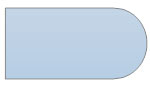
| Subroutine Symbol |
Description:Indicates a sequence of actions that perform a specific task embedded within a larger process. This sequence of actions could be described in more detail on a separate flowchart.
| Parameter | Description | Example | |
|---|---|---|---|
| Lib_FC_Dwg_Obj | jsGraphics Object that points to the drawing. | ||
| Lib_FC_Info | Array that contains the number of lines to be displayed within the Subroutine symbol, followed by
the text for each of the lines. Example: S1_Info = [ 3, "This is", "a Test", "Symbol" ];
An optional ID can be added to the end of the array for identifying the process in your
code. The ID will be located at the upper right of the symbol.S1_Info = [ 3, "This is", "a Test", "Symbol", "S1" ]; |
||
| Lib_FC_Start_X, Lib_FC_Start_Y | Center of FC Object. Object will be 120 pixels wide and 25, 40, or 55 pixels high, depending on whether there is 1, 2 or 3 lines of Info. |
Connector Points |
|
Return: Returns the X and Y connection point pairs are returned for the top-center, right-center, bottom-center, and left-center, respectively.
Usage: The sample function call is shown below. The sample draws a Subroutine rectangle and places a three line label, "This is", "a Test", "Symbol" in the center. Because 3 lines are defined, the vertical size is increased to 55 pixels to accomodate the text. A Process ID (S1) is placed outside the symbol, on the upper right side.
S1_XY_Return = [S1_Top_X, S1_Top_Y, S1_Rt_X, S1_Rt_Y, S1_Bot_X, S1_Bot_Y, S1_Lt_X, S1_Lt_Y] = Subroutine( Lib_FC_Dwg_Obj, S1_Info, S1_Start_X, S1_Start_Y );
| Manual Loop Symbol |
Description: Indicates a sequence of commands that will continue to repeat until stopped manually.
| Parameter | Description | Example | |
|---|---|---|---|
| Lib_FC_Dwg_Obj | jsGraphics Object that points to the drawing. | ||
| Lib_FC_Info | Array that contains, in order, the text for the Left, Right, and Bottom output,
followed by the text within the decision symbol. The text within the Decision symbol is split
up into several lines and includes the number of lines. Left Text ("Yes", "No", etc.), Right Text ("Yes", "No", etc.), Bottom Text ("Yes", "No", etc.), 2, "Decision", "symbol?" |
||
| Lib_FC_Width | Specifies the width of the Decision symbol. | ||
| Lib_FC_Height | Specifies the height of the Decision symbol. | ||
| Lib_FC_Start_X, Lib_FC_Start_Y | Center of FC Object. | Connector Points |
|
Return: The X and Y connection points returned for the top-center, right-center, bottom-center, and left-center, respectively
Usage: The sample function call is shown below.
IO1_Info = [ 3, "This is a test of", "the Input/Output", "Symbol"];
IO1_Return_XY = [IO1_Top_X, IO1_Top_Y, IO1_Rt_X, IO1__Rt_Y, IO1_Bot_X, IO1_Bot_Y, IO1_I_Lt_X, IO1_Lt_Y] = InOut( Lib_FC_Dwg_Obj, IO1_Info, IO1_Width, IO1_Height, IO1_Start_X, IO1_Start_Y );
| Loop Limit Symbol |
Description: Indicates the point at which a loop should stop.
| Parameter | Description | Example | |
|---|---|---|---|
| Lib_FC_Dwg_Obj | jsGraphics Object that points to the drawing. | ||
| Lib_FC_Info | Array that contains, in order, the text for the Left, Right, and Bottom output,
followed by the text within the decision symbol. The text within the Decision symbol is split
up into several lines and includes the number of lines. Left Text ("Yes", "No", etc.), Right Text ("Yes", "No", etc.), Bottom Text ("Yes", "No", etc.), 2, "Decision", "symbol?" |
||
| Lib_FC_Width | Specifies the width of the Decision symbol. | ||
| Lib_FC_Height | Specifies the height of the Decision symbol. | ||
| Lib_FC_Start_X, Lib_FC_Start_Y | Center of FC Object. | Connector Points |
|
Return: The X and Y connection points returned for the top-center, right-center, bottom-center, and left-center, respectively
Usage: The sample function call is shown below.
IO1_Info = [ 3, "This is a test of", "the Input/Output", "Symbol"];
IO1_Return_XY = [IO1_Top_X, IO1_Top_Y, IO1_Rt_X, IO1__Rt_Y, IO1_Bot_X, IO1_Bot_Y, IO1_I_Lt_X, IO1_Lt_Y] = InOut( Lib_FC_Dwg_Obj, IO1_Info, IO1_Width, IO1_Height, IO1_Start_X, IO1_Start_Y );
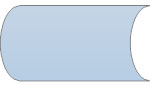
| Delay Symbol |
Description: Indicates a delay in the process.
| Parameter | Description | Example | |
|---|---|---|---|
| Lib_FC_Dwg_Obj | jsGraphics Object that points to the drawing. | ||
| Lib_FC_Info | Array that contains, in order, the text for the Left, Right, and Bottom output,
followed by the text within the decision symbol. The text within the Decision symbol is split
up into several lines and includes the number of lines. Left Text ("Yes", "No", etc.), Right Text ("Yes", "No", etc.), Bottom Text ("Yes", "No", etc.), 2, "Decision", "symbol?" |
||
| Lib_FC_Width | Specifies the width of the Decision symbol. | ||
| Lib_FC_Height | Specifies the height of the Decision symbol. | ||
| Lib_FC_Start_X, Lib_FC_Start_Y | Center of FC Object. | Connector Points |
|
Return: The X and Y connection points returned for the top-center, right-center, bottom-center, and left-center, respectively
Usage: The sample function call is shown below.
IO1_Info = [ 3, "This is a test of", "the Input/Output", "Symbol"];
IO1_Return_XY = [IO1_Top_X, IO1_Top_Y, IO1_Rt_X, IO1__Rt_Y, IO1_Bot_X, IO1_Bot_Y, IO1_I_Lt_X, IO1_Lt_Y] = InOut( Lib_FC_Dwg_Obj, IO1_Info, IO1_Width, IO1_Height, IO1_Start_X, IO1_Start_Y );
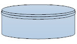
| Data Storage or Stored Data Symbol |
Description: Indicates a step where data gets stored.
| Parameter | Description | Example | |
|---|---|---|---|
| Lib_FC_Dwg_Obj | jsGraphics Object that points to the drawing. | ||
| Lib_FC_Info | Array that contains, in order, the text for the Left, Right, and Bottom output,
followed by the text within the decision symbol. The text within the Decision symbol is split
up into several lines and includes the number of lines. Left Text ("Yes", "No", etc.), Right Text ("Yes", "No", etc.), Bottom Text ("Yes", "No", etc.), 2, "Decision", "symbol?" |
||
| Lib_FC_Width | Specifies the width of the Decision symbol. | ||
| Lib_FC_Height | Specifies the height of the Decision symbol. | ||
| Lib_FC_Start_X, Lib_FC_Start_Y | Center of FC Object. | Connector Points |
|
Return: The X and Y connection points returned for the top-center, right-center, bottom-center, and left-center, respectively
Usage: The sample function call is shown below.
IO1_Info = [ 3, "This is a test of", "the Input/Output", "Symbol"];
IO1_Return_XY = [IO1_Top_X, IO1_Top_Y, IO1_Rt_X, IO1__Rt_Y, IO1_Bot_X, IO1_Bot_Y, IO1_I_Lt_X, IO1_Lt_Y] = InOut( Lib_FC_Dwg_Obj, IO1_Info, IO1_Width, IO1_Height, IO1_Start_X, IO1_Start_Y );
| Database Symbol |
Description: Indicates a list of information with a standard structure that allows for searching and sorting.
| Parameter | Description | Example | |
|---|---|---|---|
| Lib_FC_Dwg_Obj | jsGraphics Object that points to the drawing. | ||
| Lib_FC_Info | Array that contains, in order, the text for the Left, Right, and Bottom output,
followed by the text within the decision symbol. The text within the Decision symbol is split
up into several lines and includes the number of lines. Left Text ("Yes", "No", etc.), Right Text ("Yes", "No", etc.), Bottom Text ("Yes", "No", etc.), 2, "Decision", "symbol?" |
||
| Lib_FC_Width | Specifies the width of the Decision symbol. | ||
| Lib_FC_Height | Specifies the height of the Decision symbol. | ||
| Lib_FC_Start_X, Lib_FC_Start_Y | Center of FC Object. | Connector Points |
|
Return: The X and Y connection points returned for the top-center, right-center, bottom-center, and left-center, respectively
Usage: The sample function call is shown below.
IO1_Info = [ 3, "This is a test of", "the Input/Output", "Symbol"];
IO1_Return_XY = [IO1_Top_X, IO1_Top_Y, IO1_Rt_X, IO1__Rt_Y, IO1_Bot_X, IO1_Bot_Y, IO1_I_Lt_X, IO1_Lt_Y] = InOut( Lib_FC_Dwg_Obj, IO1_Info, IO1_Width, IO1_Height, IO1_Start_X, IO1_Start_Y );
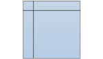
| Internal Storage Symbol |
Description: Indicates that information was stored in memory during a program, used in software design flowcharts.
| Parameter | Description | Example | |
|---|---|---|---|
| Lib_FC_Dwg_Obj | jsGraphics Object that points to the drawing. | ||
| Lib_FC_Info | Array that contains, in order, the text for the Left, Right, and Bottom output,
followed by the text within the decision symbol. The text within the Decision symbol is split
up into several lines and includes the number of lines. Left Text ("Yes", "No", etc.), Right Text ("Yes", "No", etc.), Bottom Text ("Yes", "No", etc.), 2, "Decision", "symbol?" |
||
| Lib_FC_Width | Specifies the width of the Decision symbol. | ||
| Lib_FC_Height | Specifies the height of the Decision symbol. | ||
| Lib_FC_Start_X, Lib_FC_Start_Y | Center of FC Object. | Connector Points |
|
Return: The X and Y connection points returned for the top-center, right-center, bottom-center, and left-center, respectively
Usage: The sample function call is shown below.
IO1_Info = [ 3, "This is a test of", "the Input/Output", "Symbol"];
IO1_Return_XY = [IO1_Top_X, IO1_Top_Y, IO1_Rt_X, IO1__Rt_Y, IO1_Bot_X, IO1_Bot_Y, IO1_I_Lt_X, IO1_Lt_Y] = InOut( Lib_FC_Dwg_Obj, IO1_Info, IO1_Width, IO1_Height, IO1_Start_X, IO1_Start_Y );
| Display Symbol |
Description: Indicates a step that displays information.

| Parameter | Description | Example | |
|---|---|---|---|
| Lib_FC_Dwg_Obj | jsGraphics Object that points to the drawing. | ||
| Lib_FC_Info | Array that contains, in order, the text for the Left, Right, and Bottom output,
followed by the text within the decision symbol. The text within the Decision symbol is split
up into several lines and includes the number of lines. Left Text ("Yes", "No", etc.), Right Text ("Yes", "No", etc.), Bottom Text ("Yes", "No", etc.), 2, "Decision", "symbol?" |
||
| Lib_FC_Width | Specifies the width of the Decision symbol. | ||
| Lib_FC_Height | Specifies the height of the Decision symbol. | ||
| Lib_FC_Start_X, Lib_FC_Start_Y | Center of FC Object. | Connector Points |
|
Return: The X and Y connection points returned for the top-center, right-center, bottom-center, and left-center, respectively
Usage: The sample function call is shown below.
IO1_Info = [ 3, "This is a test of", "the Input/Output", "Symbol"];
IO1_Return_XY = [IO1_Top_X, IO1_Top_Y, IO1_Rt_X, IO1__Rt_Y, IO1_Bot_X, IO1_Bot_Y, IO1_I_Lt_X, IO1_Lt_Y] = InOut( Lib_FC_Dwg_Obj, IO1_Info, IO1_Width, IO1_Height, IO1_Start_X, IO1_Start_Y );